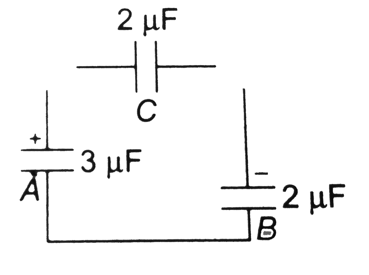
Two capacitors A and B with capacities 3μF and 2μF are charged to a potential difference of 100V and 180V, respectively. The plates of the capacitors are connected as show in figure with one wire of each capacitor free. The upper plate of A is positive and that of B is negastive. An uncharged 2μF capcitor C with lead wires falls on the free ends to complete the circuit. Calculate
a. the final charge on the three capacitors.
b. the amount of electrostatic energy stored in the system before and after completion of the circuit.
Step by step video & image solution for Two capacitors A and B with capacities 3muF and 2muF are charged to a potential difference of 100 V and 180V, respectively. The plates of the capacitors are connected as show in figure with one wire of each capacitor free. The upper plate of A is positive and that of B is negastive. An uncharged 2muF capcitor C with lead wires falls on the free ends to complete the circuit. Calculate a. the final charge on the three capacitors. b. the amount of electrostatic energy stored in the system before and after completion of the circuit. by Physics experts to help you in doubts & scoring excellent marks in Class 12 exams.
Updated on:21/07/2023Topper's Solved these Questions
- CAPACITANCEBOOK - PHYSICS GALAXY - ASHISH ARORACHAPTER - CAPACITANCEEXERCISE - DISCUSSION QUESTIONS
22 Videos
- CAPACITANCEBOOK - PHYSICS GALAXY - ASHISH ARORACHAPTER - CAPACITANCEEXERCISE - CONCEPTUAL MCQA
32 Videos
- ATOMIC PHYSICSBOOK - PHYSICS GALAXY - ASHISH ARORACHAPTER - ATOMIC PHYSICSEXERCISE - Unsolved Numerical Problems
39 Videos
- CURRENT ELECTRICITYBOOK - PHYSICS GALAXY - ASHISH ARORACHAPTER - CURRENT ELECTRICITYEXERCISE - All Questions
389 Videos
Similar Questions
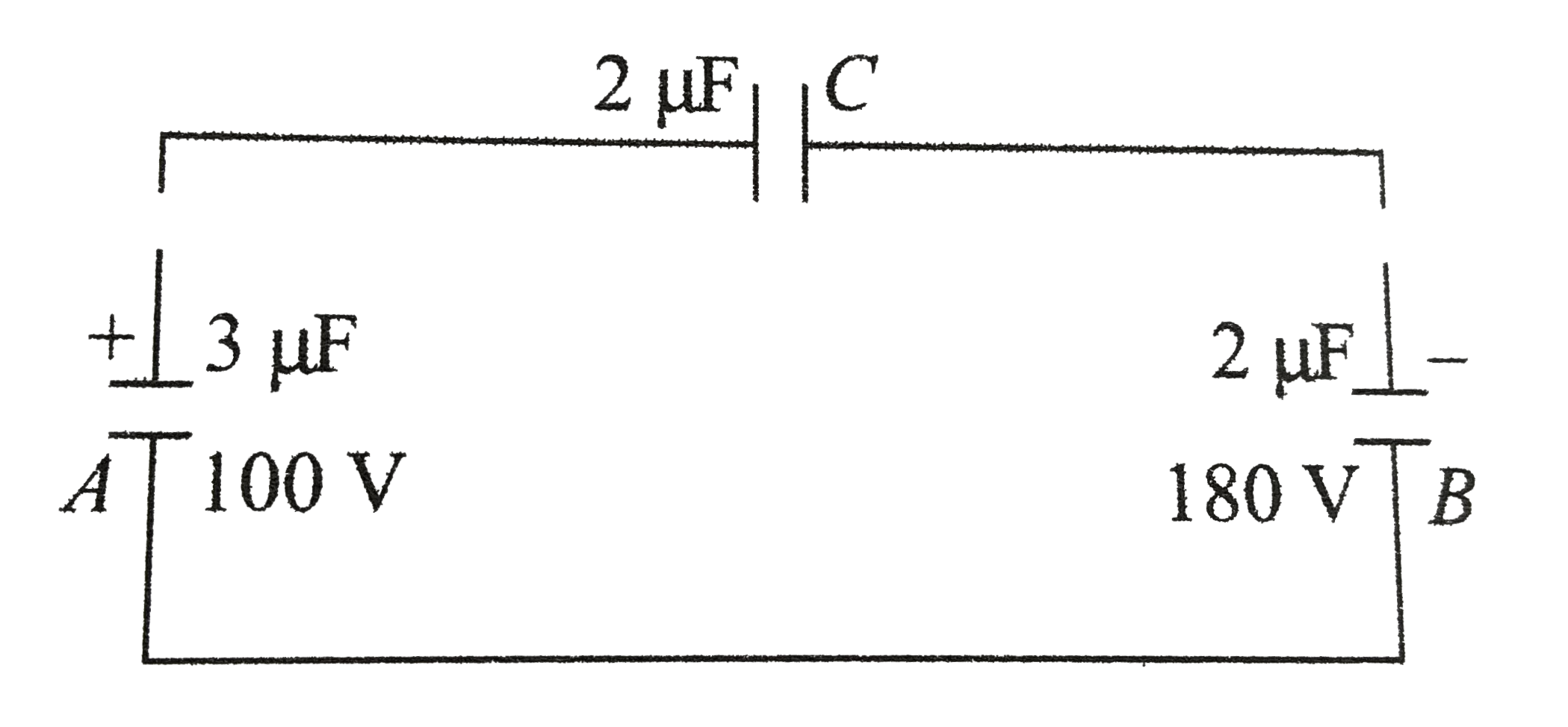
Two capacitors A and B with capacities 3μF and 2μF are charged to a potential differece of 100V and 180V, respectively. The plates ot the capacitors are connected as shown in, with one wire free from each capacitor. The upper plate of A is positive and that of B is negative An uncharged 2μF capacitor C with lead wires falls on the free ends to complete the circuit.
i. Calculate the final charge on the three capacitors,
ii. Find the amount of electrostatic energy stored in the system before and after the completion of the circuit.
 .
.
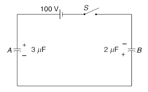
View SolutionTwo capacitors A and B with capacitors 3μFand2μF are charged to a potential difference of 100 V and 180 V respectively. One plate of two capacitors are connected as shown. Now switch S is closed so as to connect a cell of 100 V to the free plates of two capacitors.
(a) Find charge on the two capacitors after the switch is closed.
(b) Calculate heat generated in the circuit
View Solution
Knowledge Check
Two capacitors A and B with capacities C1andC2 are charged to potential difference of V1andV2 respectively. The plates of the capacitors are connected as shown in the figure with one wire free from each capacitor. The upper plate of A is positive and that of B is negative. An uncharged capacitor of capacitance C3 and lead wires falls on the free ends to complete circuit, then
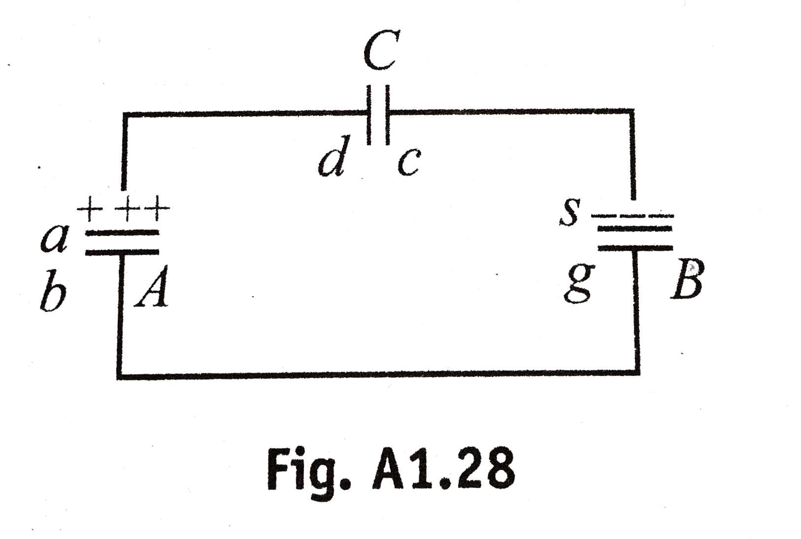 Athe final charge on each capacitor are same to each otherBthe final sum of charge on plates a and d is C1V1.Cthe final sum of charge on plates b and g is C2V2−C1V1Dboth (b) and(c ) are correct.
Two capacitors of 2μF and 3μF are charged to 150V and 120V, respectively. The plates of capacitor are connected as shown in the figure. An uncharged capacitor of capacity 1.5μF falls to the free end of the wire. Then
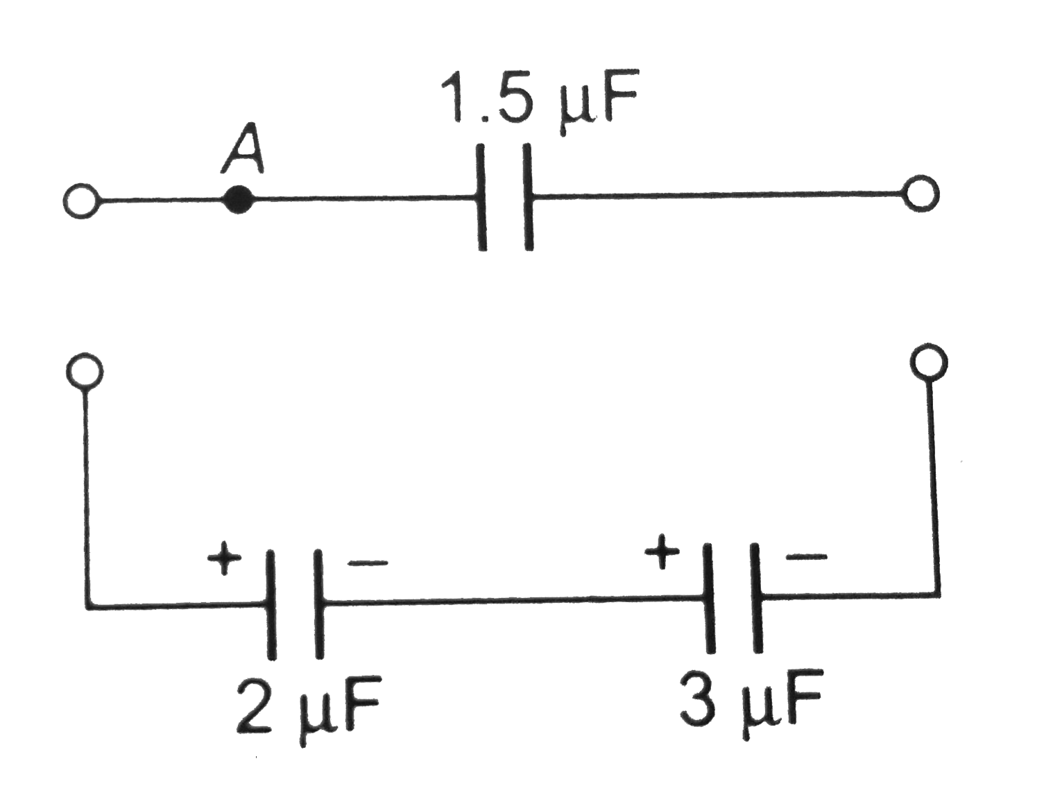 Achargeg on 1.5μF capacitor is 180μFBcharge on 2μFcapacitor is 120μFCpositive chasrge flows through A from right to leftDpositive charge flows through A from left to right
Two capacitors of capacitances 10μFand20μF are connected in series across a potential difference of 100V. The potential difference across each capacitor is respectively
A66.67 V, 33.33 VB60 V, 40 VC50 V, 50 VD90 V, 10 V
Two capacitors of capacitances 3μFand6μF, are charged to potentials 2V and 5V respectively. These two charged capacitors are connected in series. Find the potential across each of the two capacitors now.
View SolutionTwo capacitors of capacitance 10 μF and 20 μF are charged to potential 20 V and 10 V respectively. If they are connected to share charges, then loss of energy is
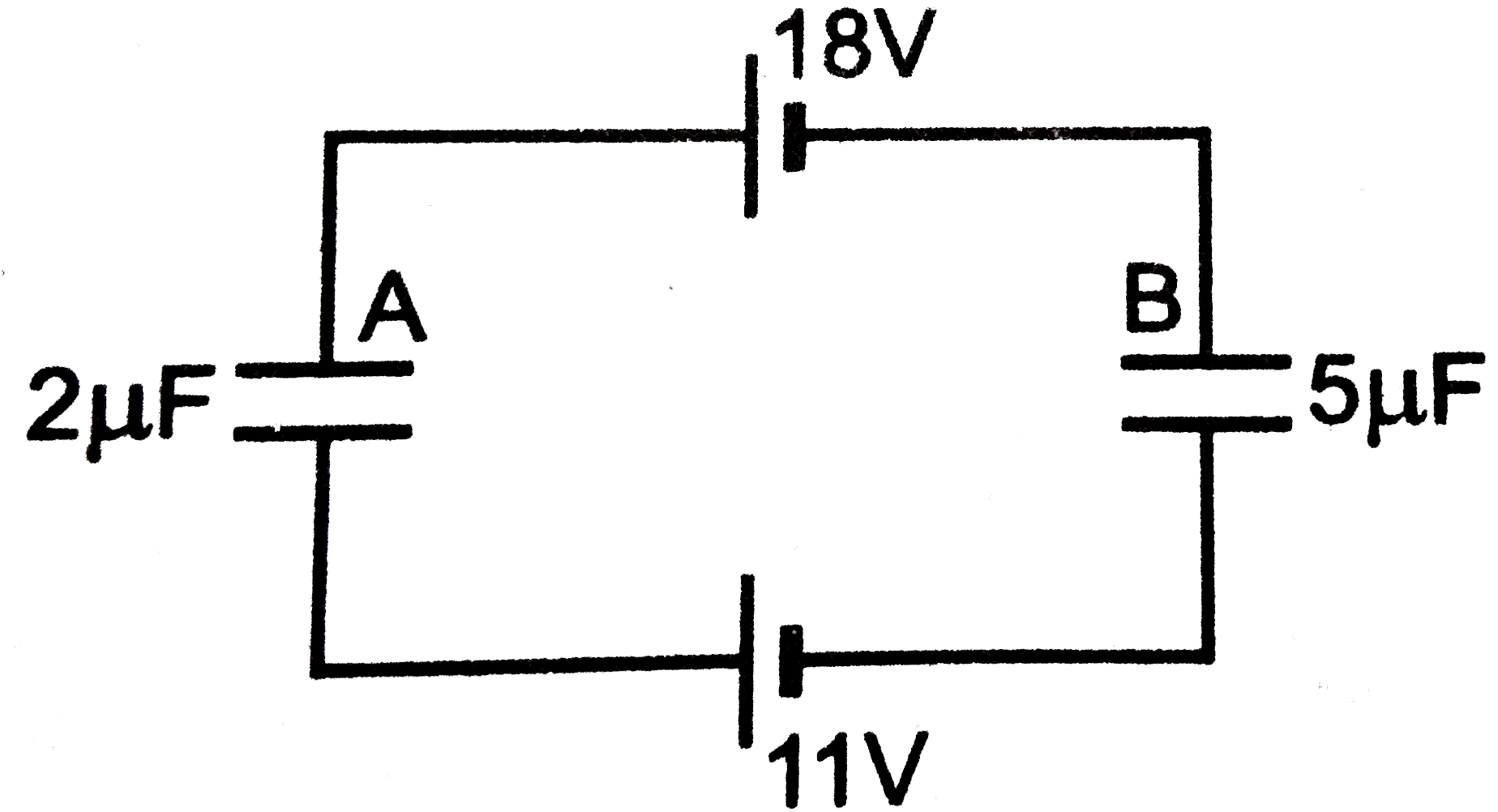
View SolutionTwo capacitors A and B of capacitances 2μF and 5μF are connected to two battery as shown in figure The potential difference in volt between the plate of A is
View SolutionA and B are two condensers of capacities 2μF and 4μF. They are charged to potential differences of 12V and 6V respectively. If they are now connected (+ve to +ve), the charge that flows through the connecting wire is
View SolutionTwo capacitors of capacitance 2μFand5μF are charged to a potential difference 100V and 50 V respectively and connected such that the positive plate of one capacitor is connected to the negative plate of the other capacitor after the switch is closed, the initial current in the circuit is 50 mA. the total resistance of the connecting wires is (in Ohm):
View Solution
