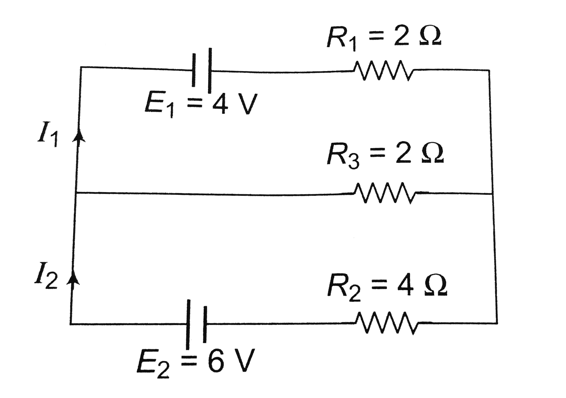
In the circuit shown below E1=4.0V,R1=2Ω,E2=6.0V,R2=4Ω and R3=2Ω. The current I1 is
1.6A
1.8A
1.25A
1.0A
The correct Answer is:B
Step by step video, text & image solution for In the circuit shown below E_(1) = 4.0 V, R_(1) = 2 Omega, E_(2) = 6.0 V, R_(2) = 4 Omega and R_(3) = 2 Omega. The current I_(1) is by Physics experts to help you in doubts & scoring excellent marks in Class 12 exams.
Topper's Solved these Questions
- BOOK - ERRORLESS CHAPTER - CURRENT ELECTRICITYEXERCISE - Kirchhoff s Law, cells8videos
CURRENT ELECTRICITY
- BOOK - ERRORLESS CHAPTER - CURRENT ELECTRICITYEXERCISE - Different Measuring Instruments1videos
CURRENT ELECTRICITY
- BOOK - ERRORLESS CHAPTER - COMMUNICATION SYSTEMEXERCISE - S E T14videos
COMMUNICATION SYSTEM
- BOOK - ERRORLESS CHAPTER - ELECTRO MAGNETIC INDUCTIONEXERCISE - SET20videos
ELECTRO MAGNETIC INDUCTION
Similar Questions
Knowledge Check
- Question 1 - Select One
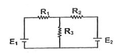
In the circuit shown, E1=7V,E2=7V,R1=R2=1Ω and R3=3Ω respectively. The current through the resistance R3
 A0.083333333333333B3.5 AC1.75 ADnone of these
 - Question 2 - Select One or More
In the circuit shown, E1=7V,E2=7V,R1=R2=1Ω and R3=3Ω respectively. The current through the resistance R3
 Ai=0Bi=2ACV=14VDV=7V
 - Question 3 - Select One
In the circuit shows in Fig E=15V, R1=1Ω, R2=1Ω, R3=2Ω, and L=1.5H. The currents flowing through R1,R2,and R3 are i1,i2, and i3, respectively.
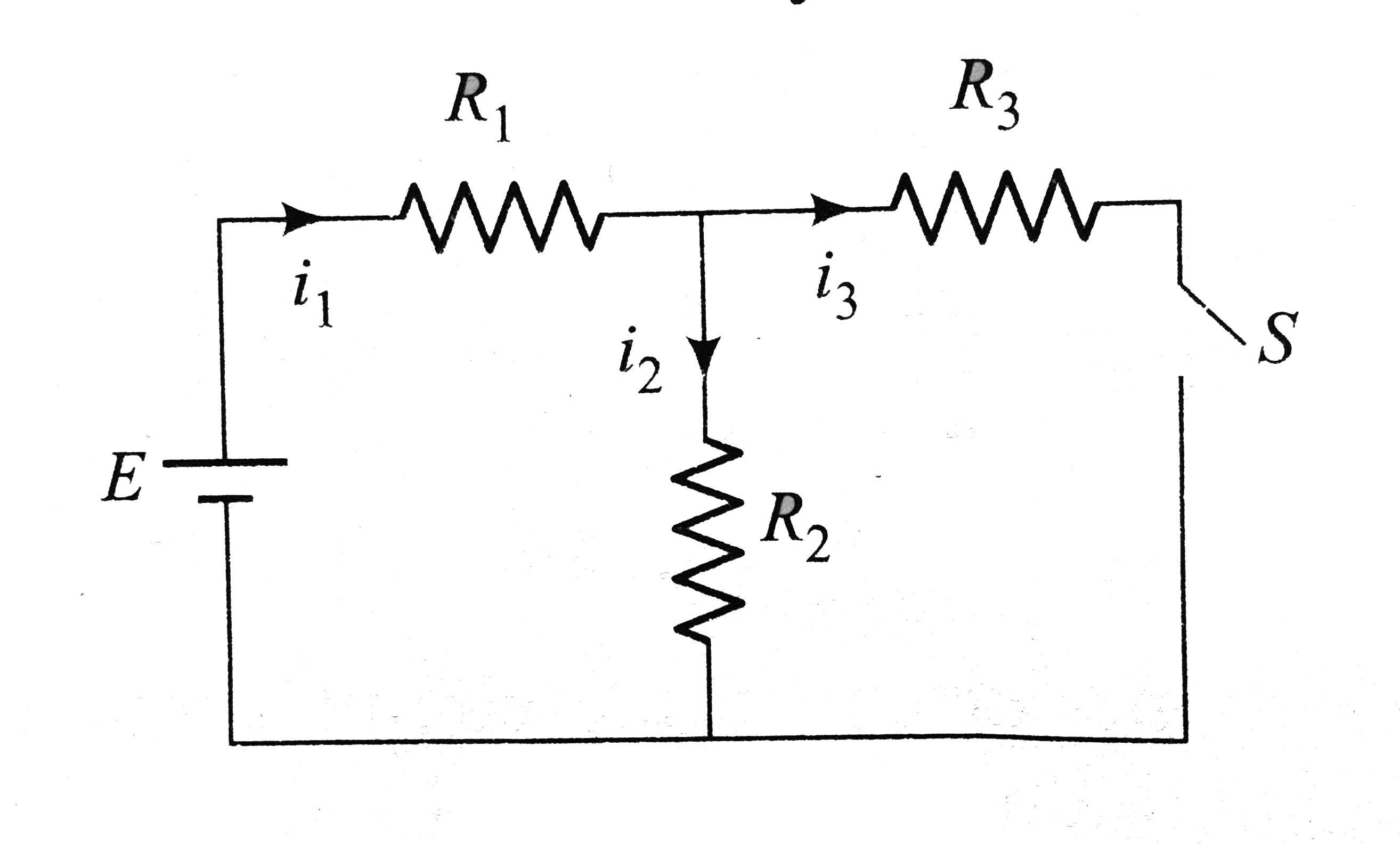
After the circuit reaches the steady state,Ai1=9A, i2=6A, i3=3ABi1=9A, i2=3A, i3=6ACi1=6A, i2=6A, i3=0ADi1=0A, i2=0A, i3=0A
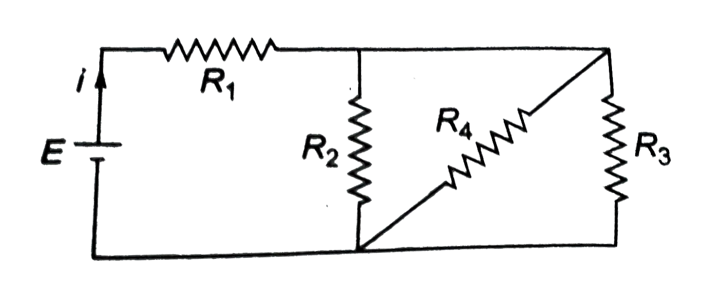
In the circuit given E = 6.0 volt, R1=100Ω,R2=R3=50Ω and R4=75Ω. The equivalent resistance of the circuit, in ohms is
 View Solution
Find a potentail difference φ1−φ2 between points 1 and 2 of the circuit shown in Fig if R11=10Ω,R2=20Ω,E1=5.0V, and E2=2.0V. The internal resisances of the current sources are negligible.
 View Solution
In the circuit shows in Fig E=15V, R1=1Ω, R2=1Ω, R3=2Ω, and L=1.5H. The currents flowing through R1,R2,and R3 are i1,i2, and i3, respectively.
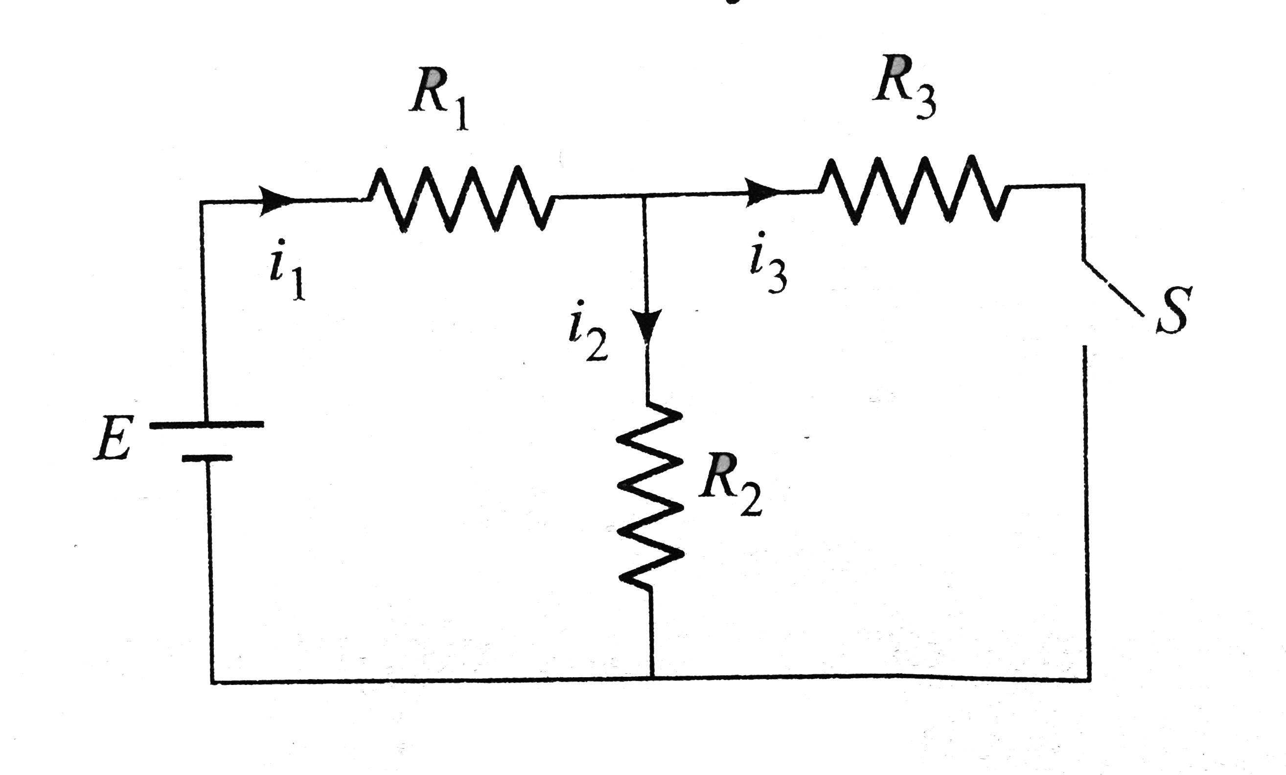
Immediately after tuning switch S on,View SolutionIn the circuit shows in Fig E=15V, R1=1Ω, R2=1Ω, R3=2Ω, and L=1.5H. The currents flowing through R1,R2,and R3 are i1,i2, and i3, respectively.
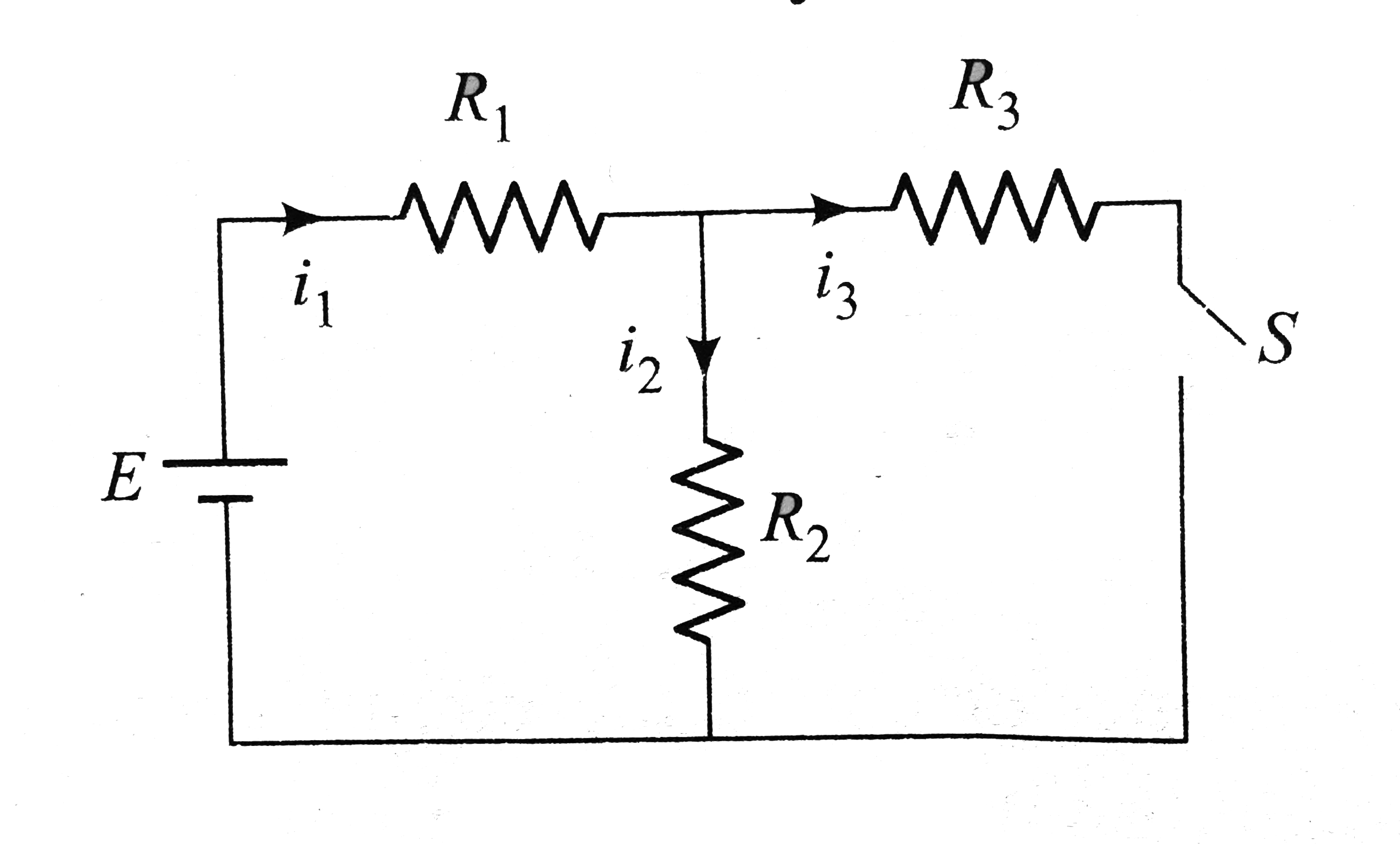
Immediately after connecting switch S,View SolutionIn the circuit shown in adjoining fig E =10V, R1=1ΩR2=2Ω,R3=3ΩandL=2H. Calculate the value of current i1,i2andi3 immidiately after key S is closed :-
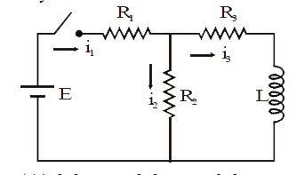 View Solution


