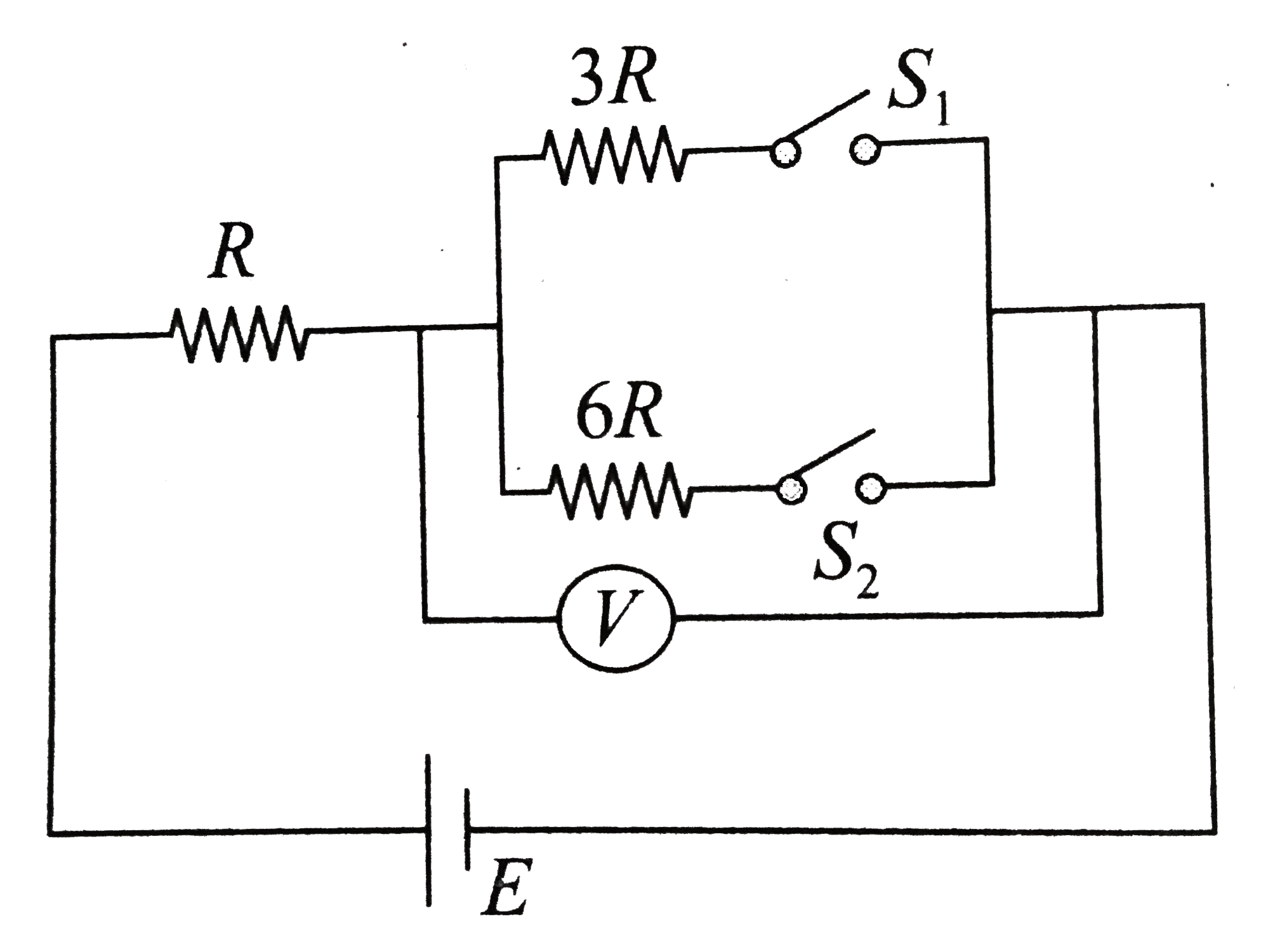
In the circuit shown in figure, reading of voltmeter is when only is closed, reading of voltmeter is when only is closed, and reading of voltmeter is when both are closed. Then .
about
EMF across
EMF across
EMF across
Topper's Solved these Questions
Similar Questions
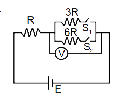
In the circuit shown in figure reading of voltmeter is V1 when only S1 is closed , reading of voltmeter is V2 when only S2 is closed . The reading of voltmeter is V3 when both S1 and S2 are closed then
 View Solution
In the circuit shown in the figure, reading of ammeter is I1 when only S1 is closed, reading of of ammeter is is I2 when only S2 is closed and reading of Ammeter,is I3 when both S1 and S2 are closed then
_PHY_E05_114_Q01.png) .View Solution
.View Solution
Knowledge Check
- Question 1 - Select One
In the circuit shown in the figure, the voltmeter reading is
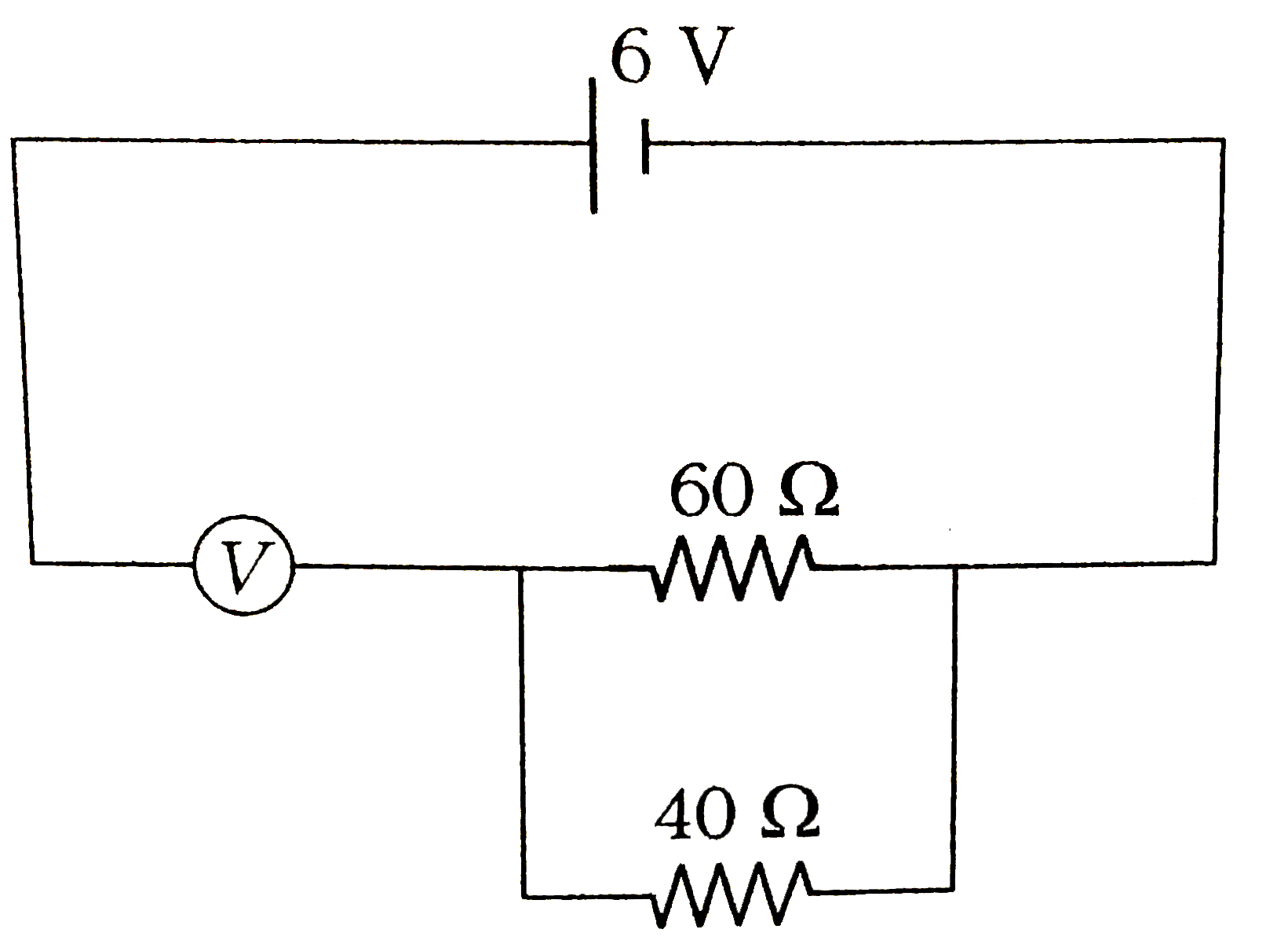 A2.4VB3.4VC4.0VD6.0V
 - Question 2 - Select One
Iri the circuit shown in figure-3.334, the resistance of voltmeter is6kΩ. The voltmeter reading will be :
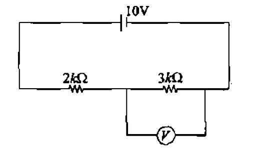 A6VB5VC4VD3V
In the circuit shown below. The reading of the voltmeter V is
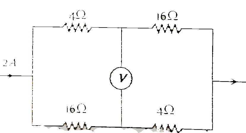 View Solution
In the circuit shown in the figure, the reading of the voltmeter is V1 when only S1 is closed,V2 when only S2 is closed and V3 when both S1andS2 are closed. From this we can conclude that
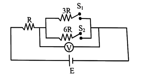 View Solution
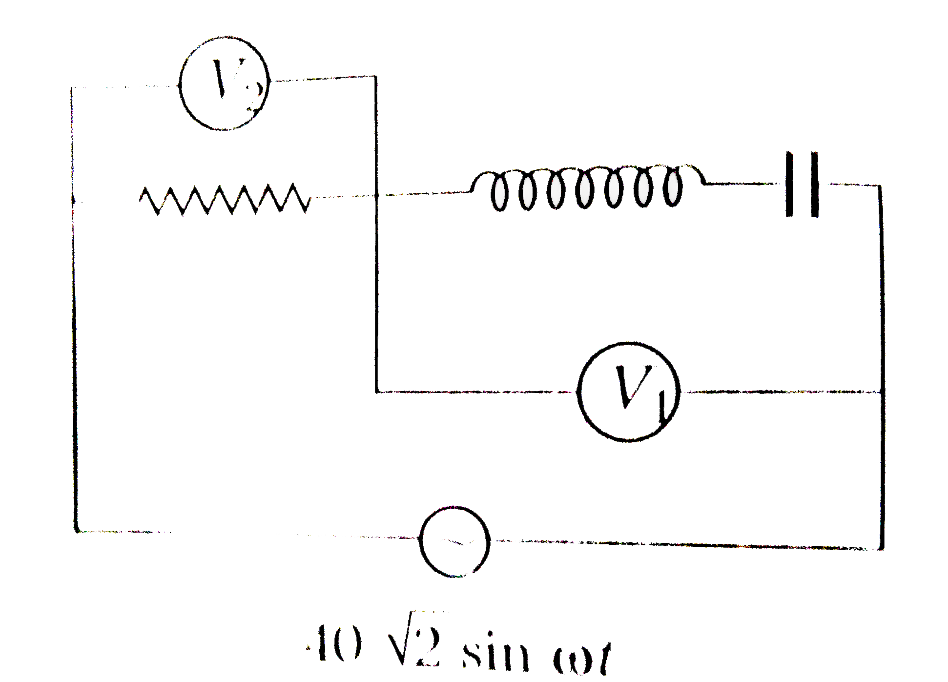
If reading of voltmeter V1 is 40 V, what is the reading of voltmeter V2?
View SolutionIn the circuit shown, the readings of voltmeters V1,V2andV3 are given by
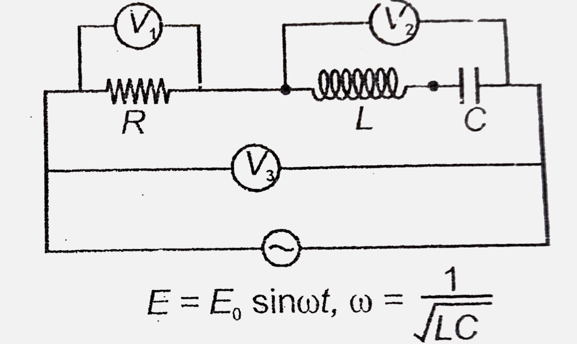 View Solution
If the reading of volmeter V1 is 30 V, what is the reading of voltmeter V2 ?
 View Solution
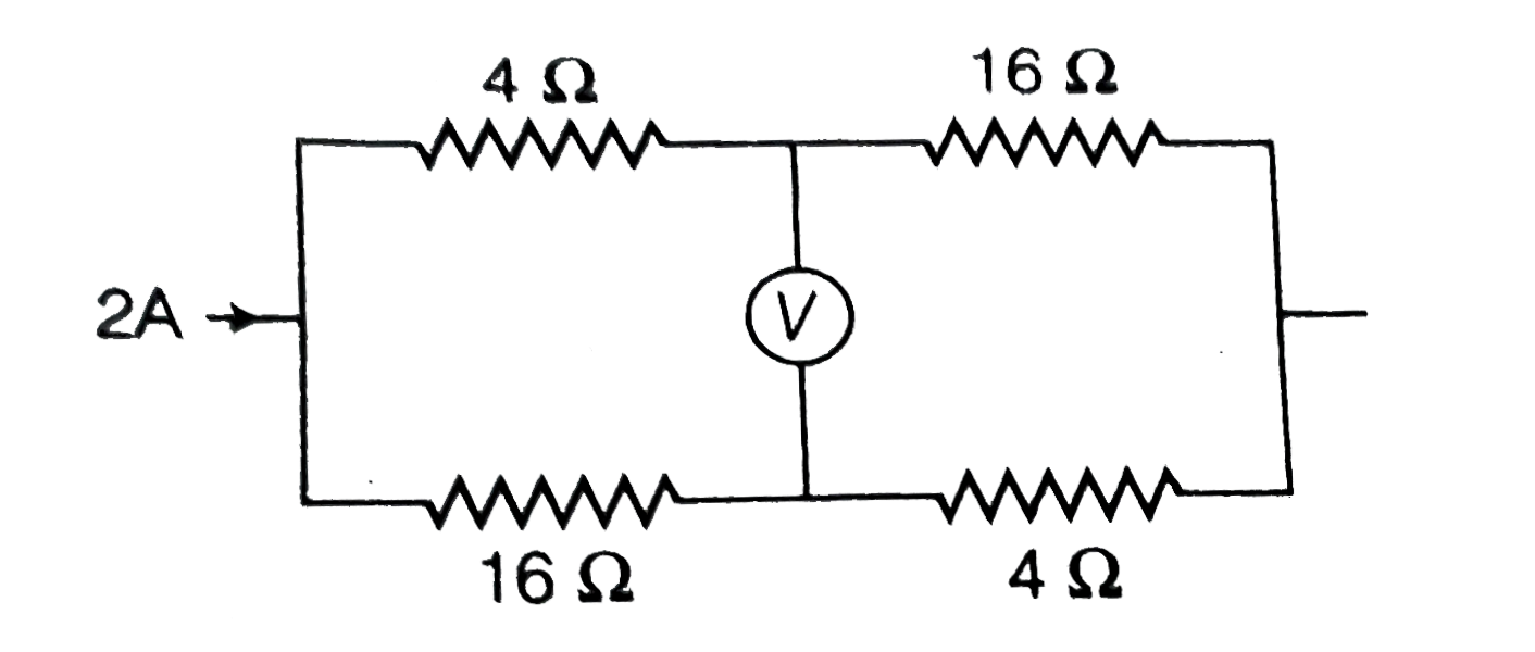
In the following circuit reading of voltmeter V is
 View Solution

