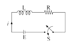
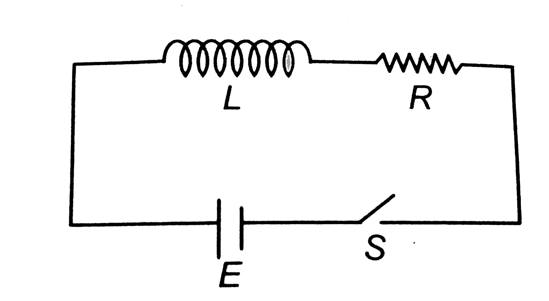
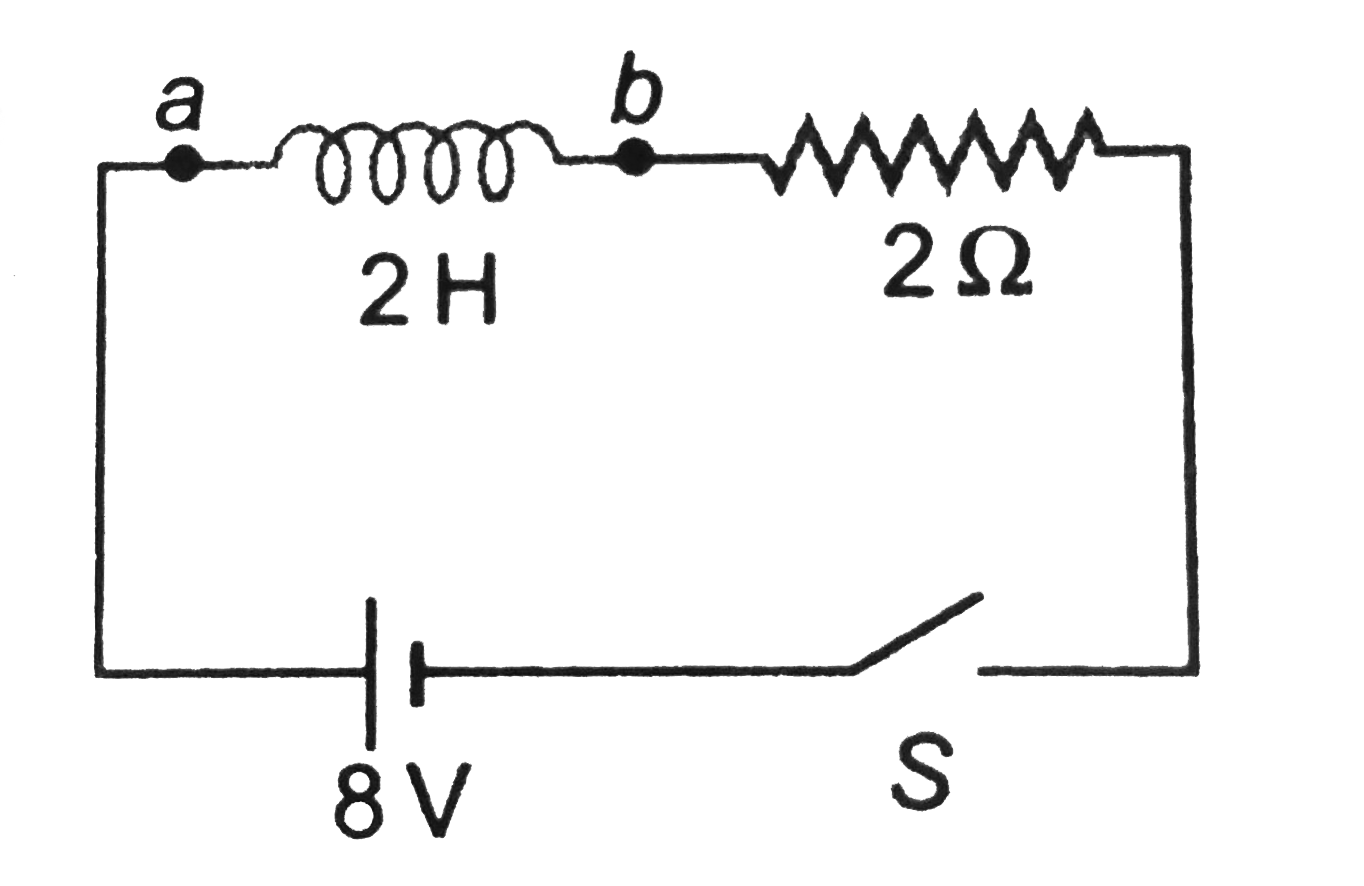
In the circuit shown in figure switch S is closed at time t=0. The charge which passes through the battery in one time constant is
A
eR2EL
B
E=(LR)
C
ELeR2
D
eLER
Video Solution
Text Solution
The correct Answer is:C
The current at time t is given by i=i0(1−e−t/τ)
Here i0=ER and τ=LR
∴q=∫τ0idt=∫t0i0(1−e−t/τ)dt
=i0τe=(ER)(LR)e=ELeR2
|
Topper's Solved these Questions
- ELECTRO MAGNETIC INDUCTIONBOOK - NARAYNACHAPTER - ELECTRO MAGNETIC INDUCTIONEXERCISE - Level-I(H.W)
23 Videos
- ELECTRIC CHARGES AND FIELDSBOOK - NARAYNACHAPTER - ELECTRIC CHARGES AND FIELDSEXERCISE - EXERCISE -4
43 Videos
- ELECTRO MAGNETIC WAVESBOOK - NARAYNACHAPTER - ELECTRO MAGNETIC WAVESEXERCISE - LEVEL-II(H.W)
14 Videos
Similar Questions
Knowledge Check
An inductance L and and a resistance R are connected in series to a battery of voltage V and negligible internal resistance through a switch. The switch is closed at t=0. The charge that passes through the battery in one time constant is [e is base of natural logarithms]
AeR2VLBVLRCVLeR2DeLVRIn the circuit shown in figure switch S is closed at time t=0, which statement is true after one time constant of L-R circuit?
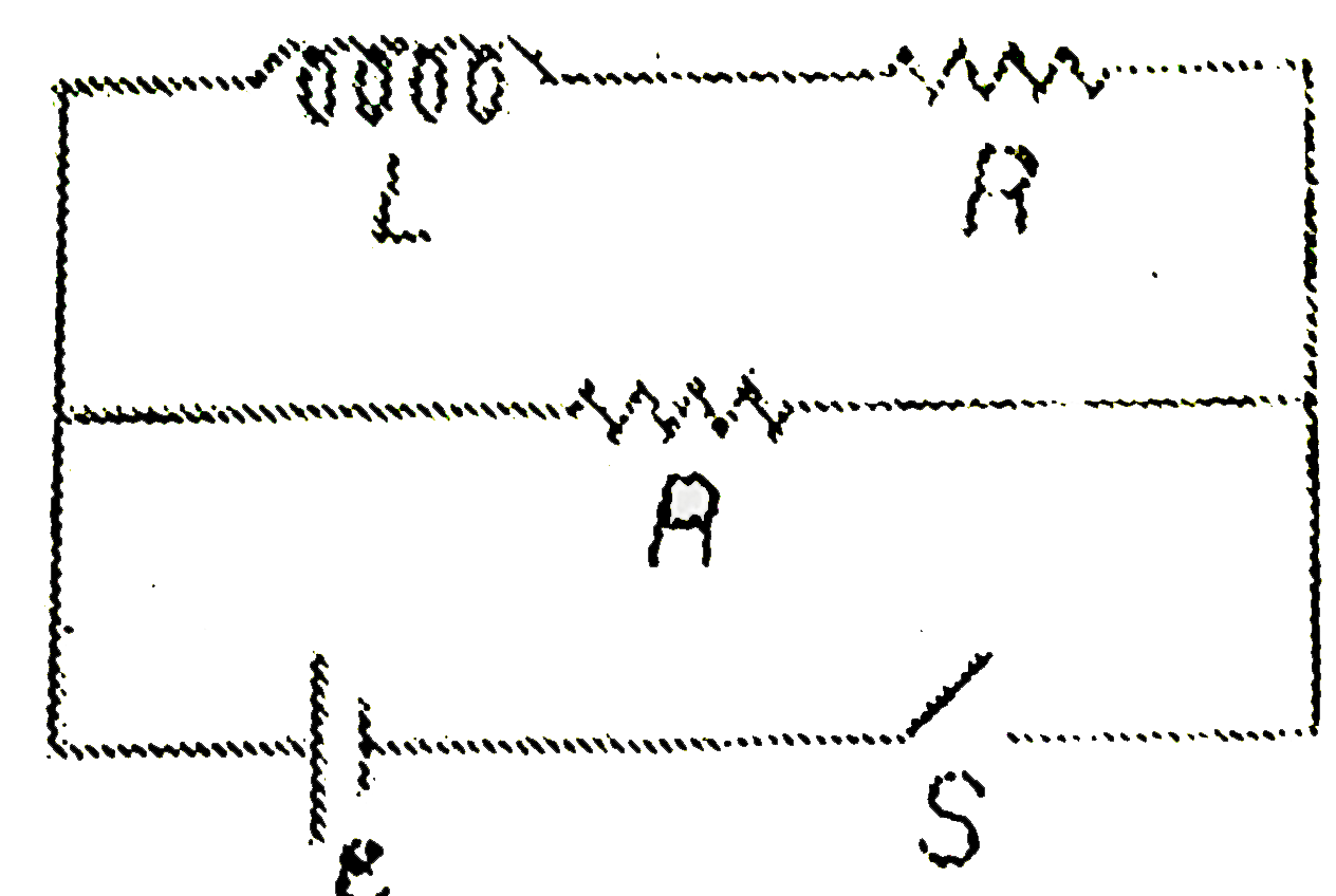 Acharge passes through inductor 2LεR(1−e−1)Bcurrent through battery ε2R(1−e−1)Ccharge passes through inductor LεR2(e−1)DCurrent through battery is 2εR
In the circuit shown in the figure, switch S is closed at time t=0. Select the correct statements.
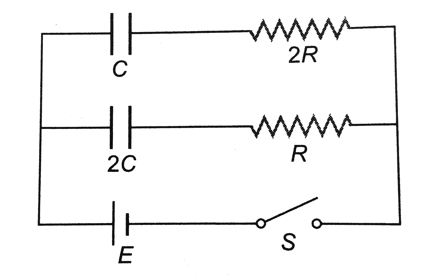 ARate of increase of charge is same in both the capacitorsBRatio of charge stored in capacitors C and 2C at any time t would be 1:2CTime constants of both the capacitors are equalDSteady state chares on capacitors C and 2C are in the ratio of 1:2
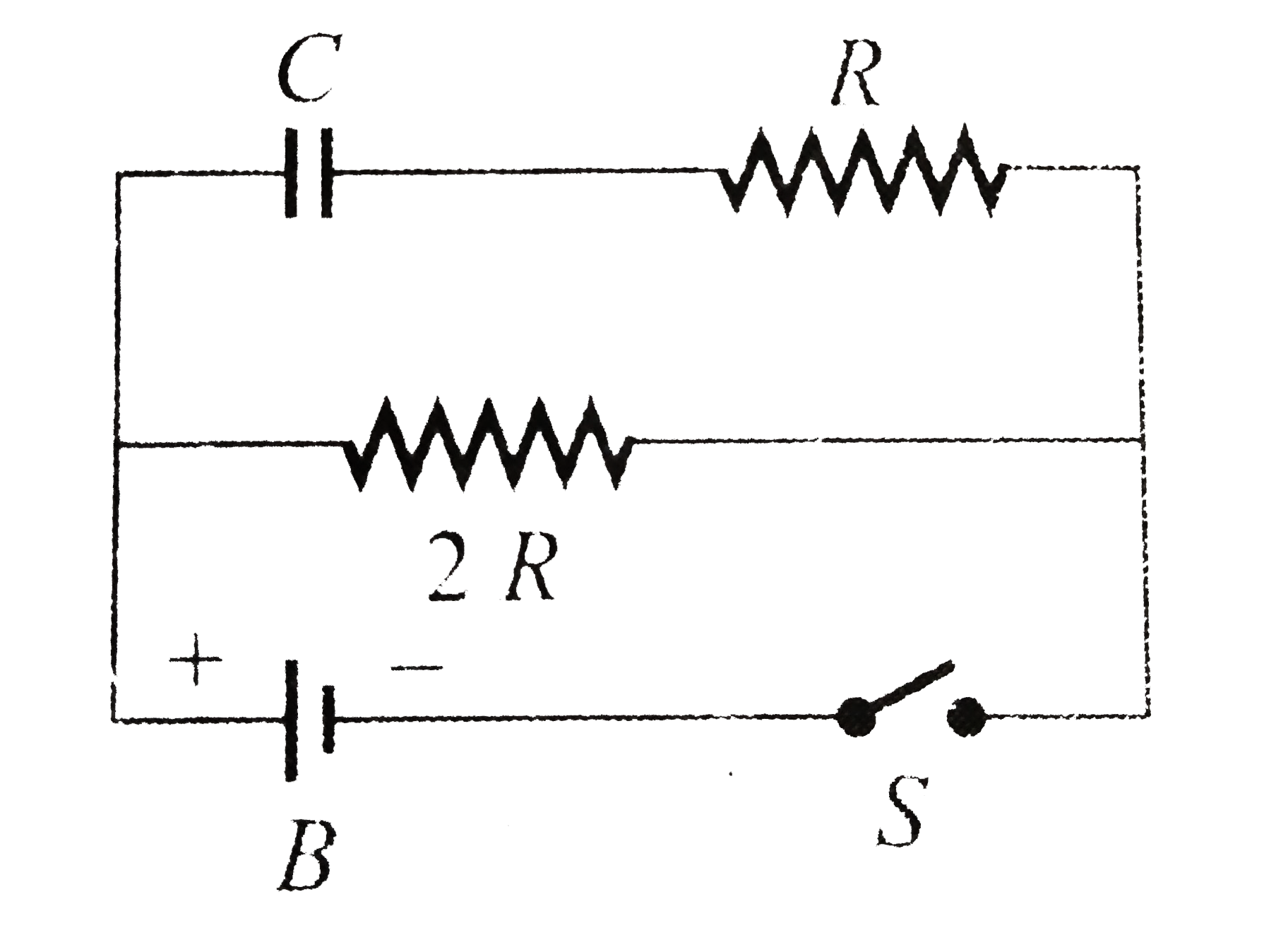
In the circuit shown in fig, if the switch S is closed at t=0 , the capacitor charges with a time constant
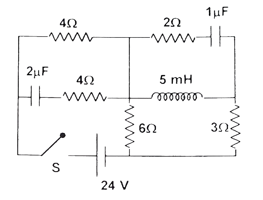
View SolutionIn the circuit shown, the switch 'S' is closed at t=0. Then the current through the battery steady state reached is
View Solution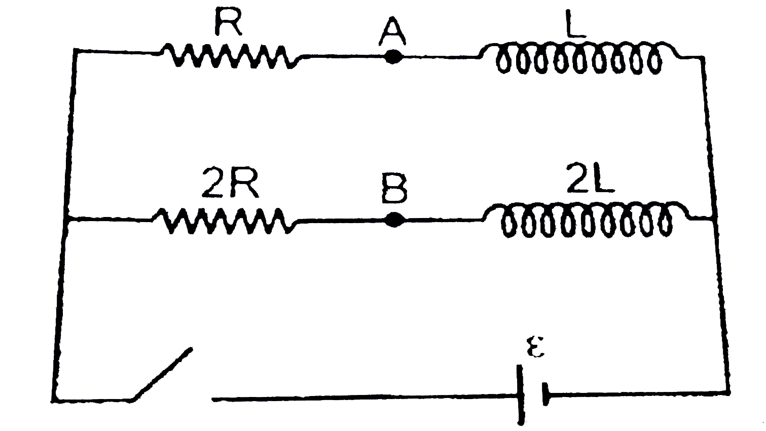
In given LR circuit the switch S is closed at time t=0 then
View SolutionIn the circuit shown in figure, circuit is closed at time t=0. At time t=ln(2) second
View SolutionIn the circuit as shown in figure the switch is closed at t=0.
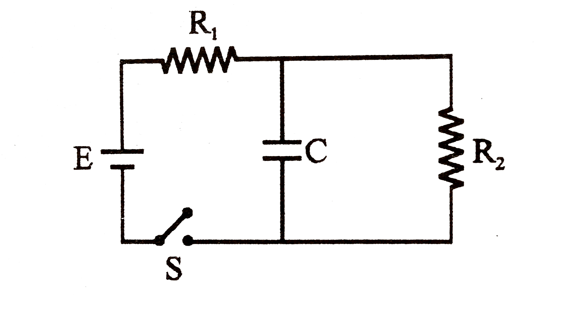
A long time after closing the switch
View Solution

