A thin uniform rod of mass m and length L is hinged at one end and from other end a light string is attached. The string is wound over a friction less pulley (having mass 2m) and a block of mass 2m is connected to string on other side of pulley as shown. the system is released from rest when the rod is making an angle of 37∘ with horizontal. Based on above information answer the following question :
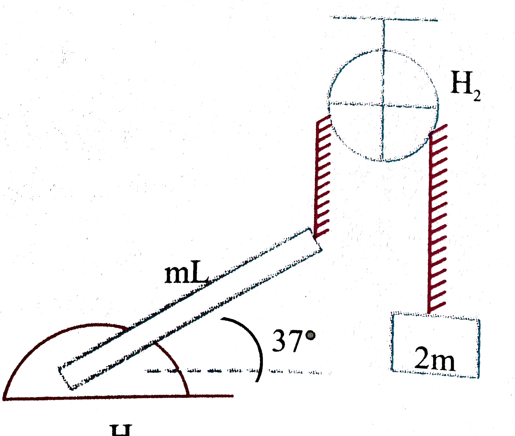
Just after release of the system from rest acceleration of block is
0.7mg
0.92mg
0.53mg
mg
The correct Answer is:C
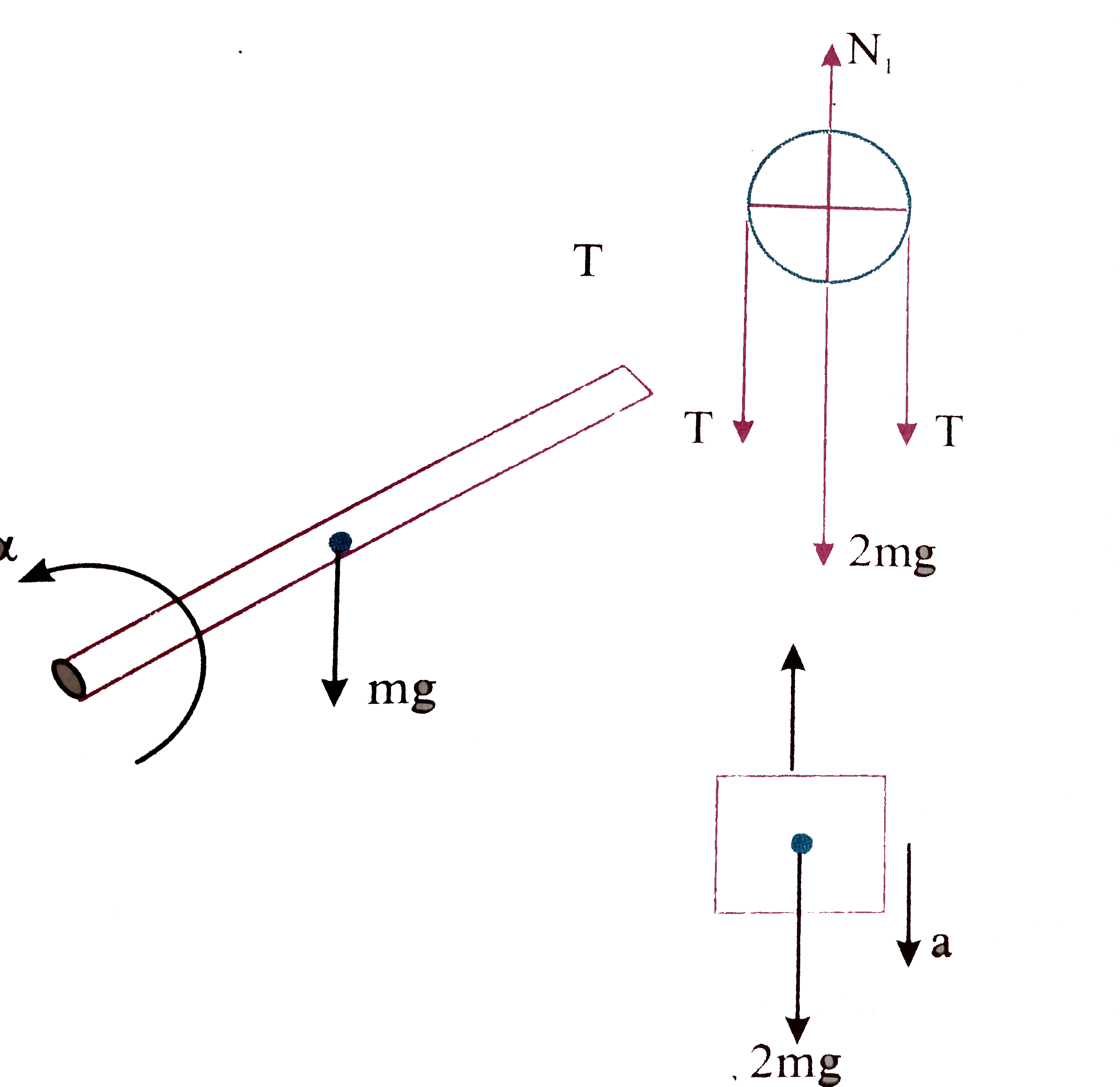
Let α be the angular acceleration of rod about hinge and a be the acceleration of block just after the system is released from rest.
The free body diagram of rod, pulley and block are shown in figure. in free body diagram of rod, the forece exerted by hinge on rod is not shown. For rod, mg×L2cos37∘−T×Lcos37∘
=−Iα[I=mL23]
For block, 2mg−T=2ma
From constraint, a=Iαcos37∘=4Lα5
Solving above equations, we get
a=72g121,α=90g121L,T=98mg121
Reactions force exerted by H2 on pulley
is, N1=2T+2mg=438121mg
Now draw the complete fee body diagram of rod as follows
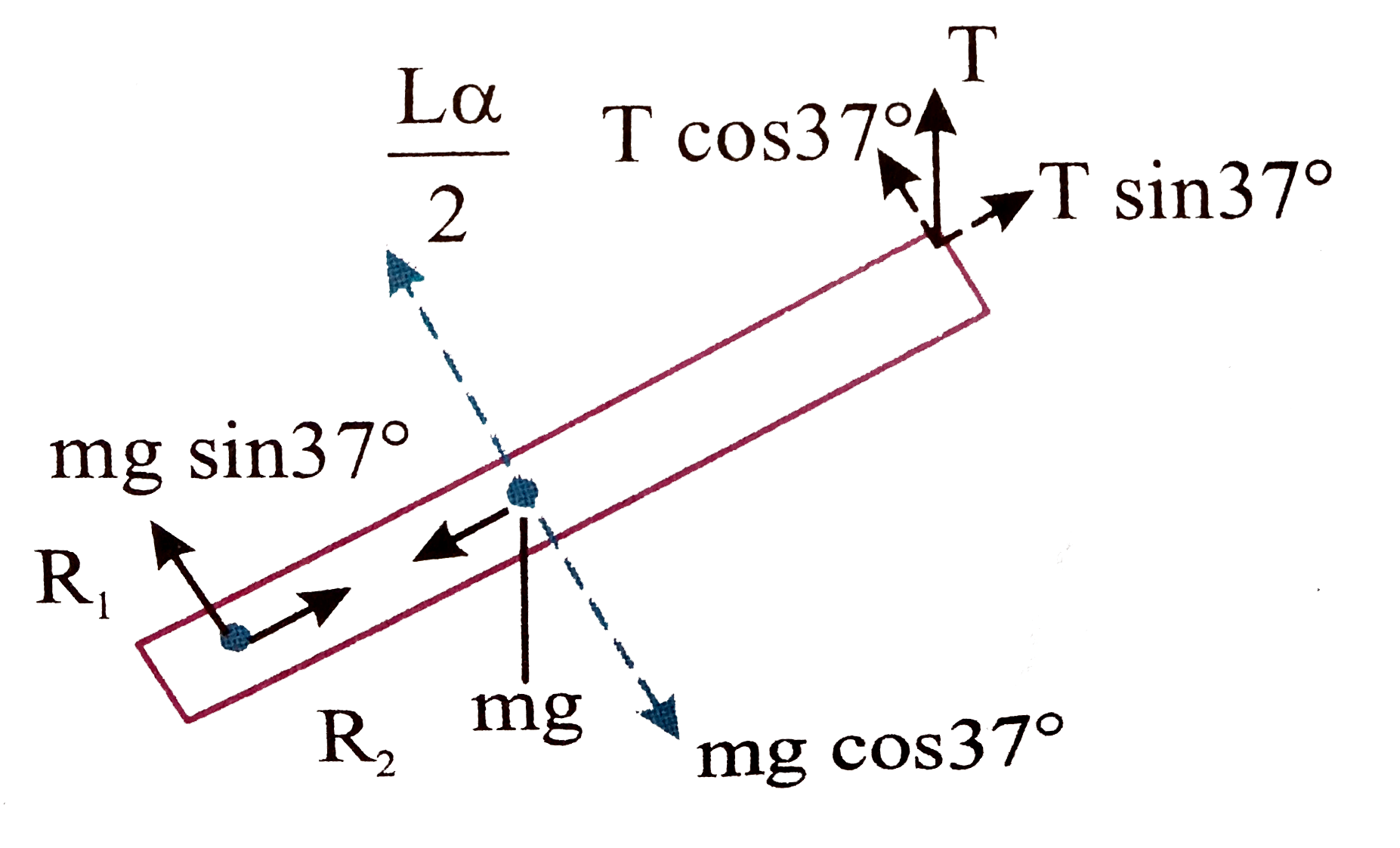
⇒R1+Tcos37∘−mgcos37∘=mL2α
⇒R2+Tsin37∘=mgsin37∘
Net reactions force on rod due to hinge is,
F=√R21+R22
Topper's Solved these Questions
- SYSTEM OF PARTICLESBOOK - NARAYNACHAPTER - SYSTEM OF PARTICLESEXERCISE - Level-VI
78 Videos
- SYSTEM OF PARTICLESBOOK - NARAYNACHAPTER - SYSTEM OF PARTICLESEXERCISE - Level -II(H.W)
47 Videos
- PHYSICAL WORLDBOOK - NARAYNACHAPTER - PHYSICAL WORLDEXERCISE - C.U.Q
10 Videos
- SYSTEM OF PARTICLES AND ROTATIONAL MOTION BOOK - NARAYNACHAPTER - SYSTEM OF PARTICLES AND ROTATIONAL MOTION EXERCISE - EXERCISE - IV
39 Videos
Similar Questions
A block of mass m can slide freely in a slot made in a bigger of mass M as shown in fig. There is no friction anywhere in the system.
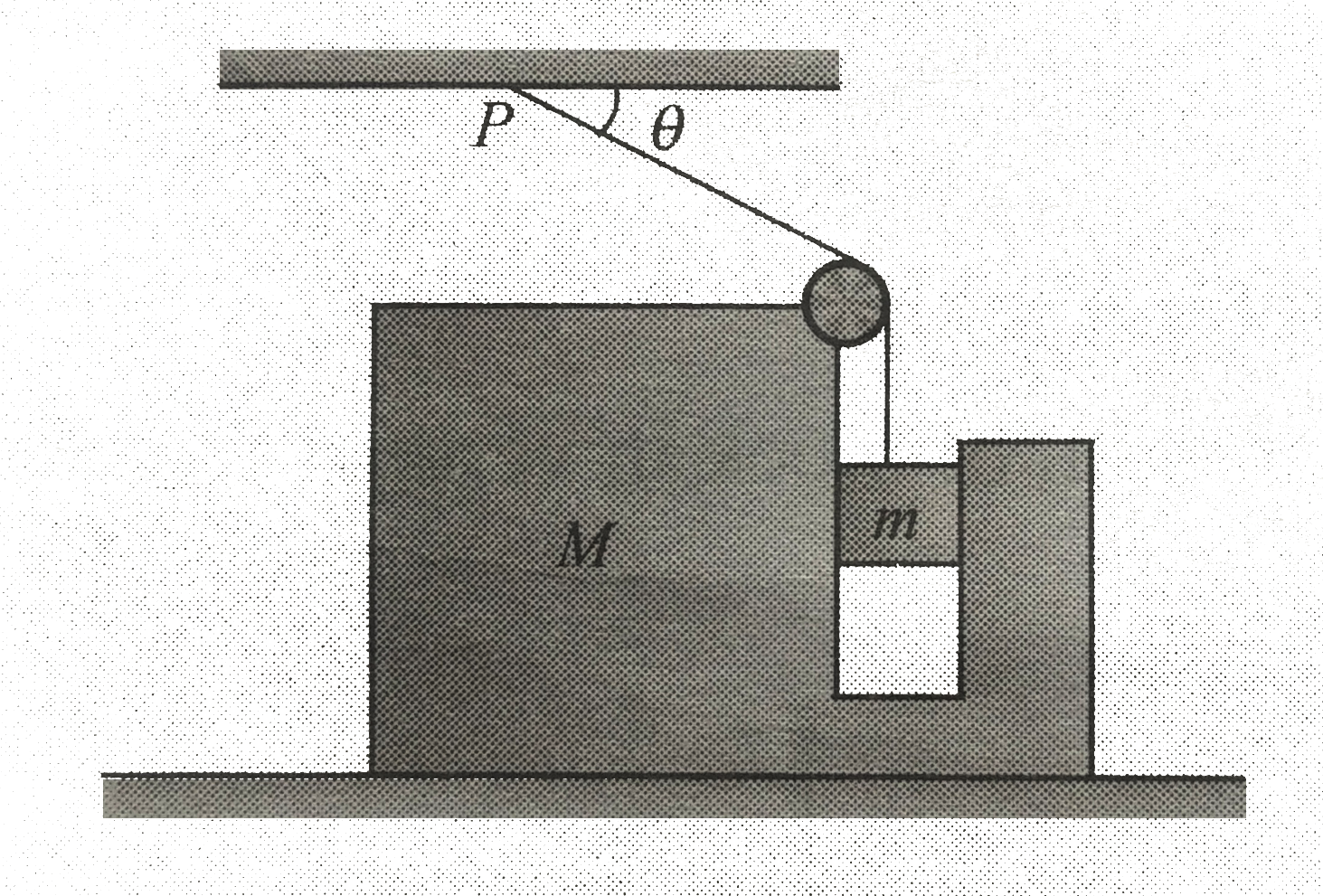
The block m is connected to one end of a string whose other end is fixed at point P. system is released from rest when the string at P makes an angle θ with horizontal. Find the acceleration of m and M after release.
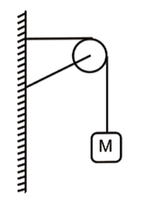
View SolutionA mass string going over a clamped pulley of mass m supports a block of mass M as shown in the figure. The force on the pulley by the clamp is given
View Solution
Knowledge Check
A thin uniformed rod of mass m and length L is hinged at one end and from other end a light string is attached. The string is wound over a frictionless pullely (having mass 2m) and a block of mass 2m is connected to string on other side of pulley as shown. the system is released from rest when the rod id making an angle of 37∘ with horizontal. Based on above information answer the following question :

Just after releases of the system from rest acceleration of block isA72g121, downwardsB48g119, downwardsC90g121, downwardsD90g121,upwardsA uniform rod of mass m and length l is hanged by two stirngs as shown in figure. Suddenly one string is cut. The tension in other string at this instant is
 A4MgBMg6CMg3DMg4
A uniform rod of mass m length l is attached to smooth hinge at end A and to a string at end B as shown in figure. It is at rest. The angular acceleration of the rod just after the string is cut is :
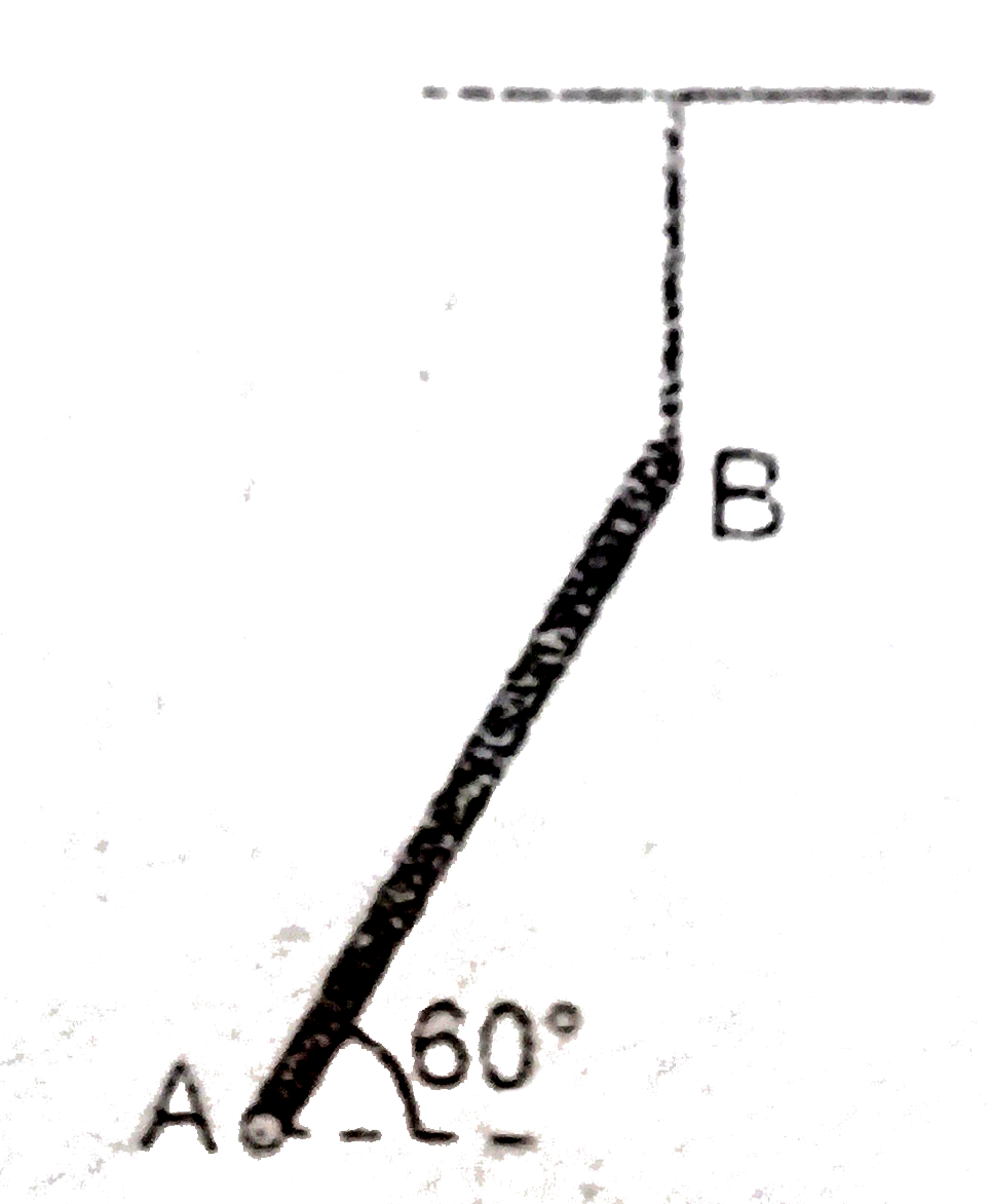 A3g2lB3g4lC5g4lD5g2l
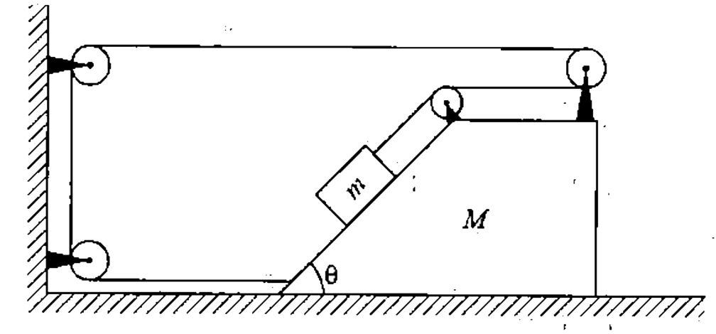
Figure-2.64 shows a block of mass M supporting a bar of mass m through a pulley system. If system is released from rest, find the acceleration of block M and the tension in the strings
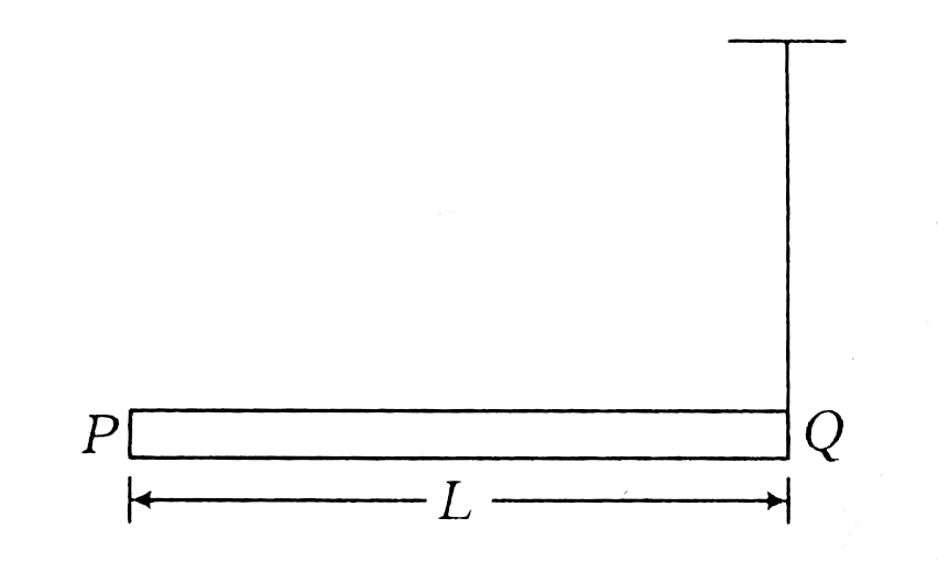
View SolutionA rod PQ of mass M and length L is hinged at end P. The rod is kept horizontal by a masseless string tied to point Q as shown in Fig. When string is cut, the initial angular acceleration of the rod is :
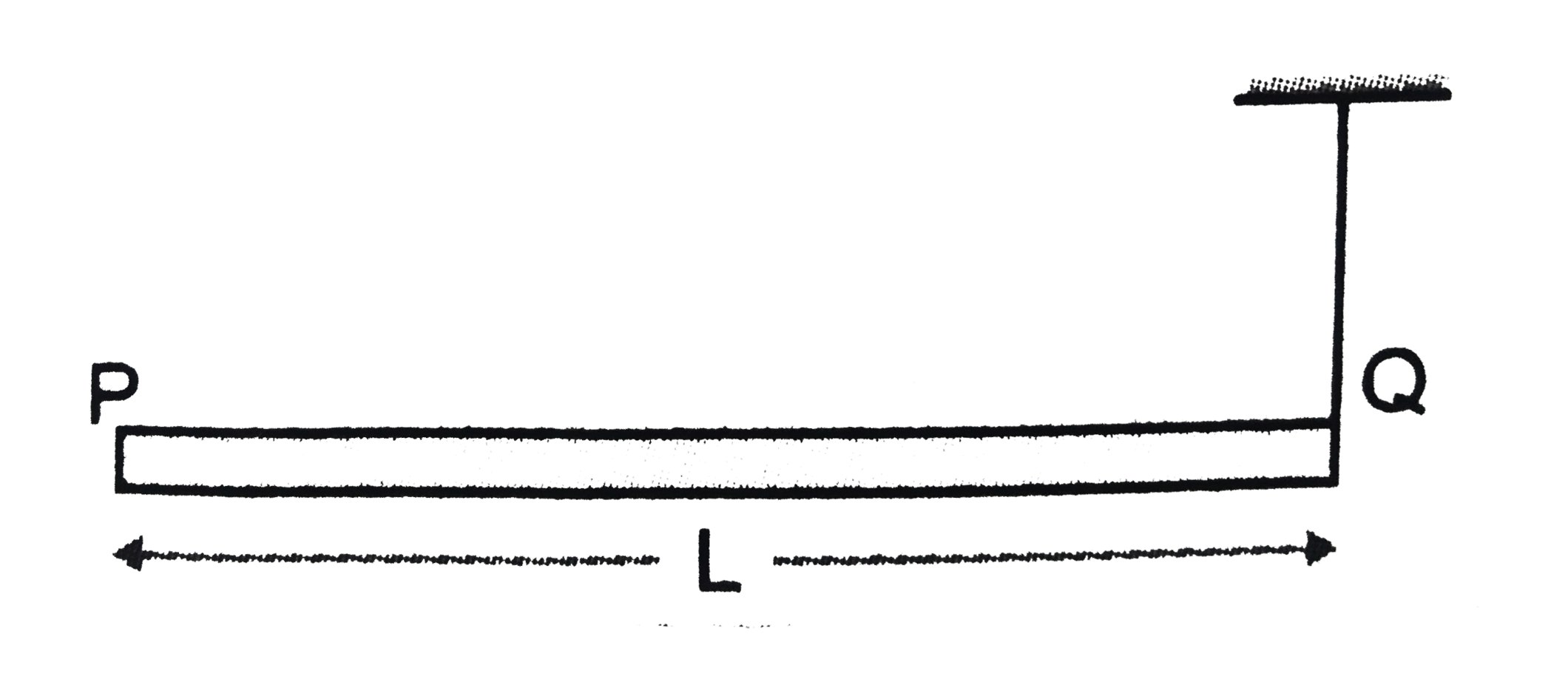
View SolutionA rod PQ of mass M and length L is hinged at end P. The rod is kept horizontal by a massless string tied to point Q as shown in figure. When string is cut, the intial angular acceleration of the rod is
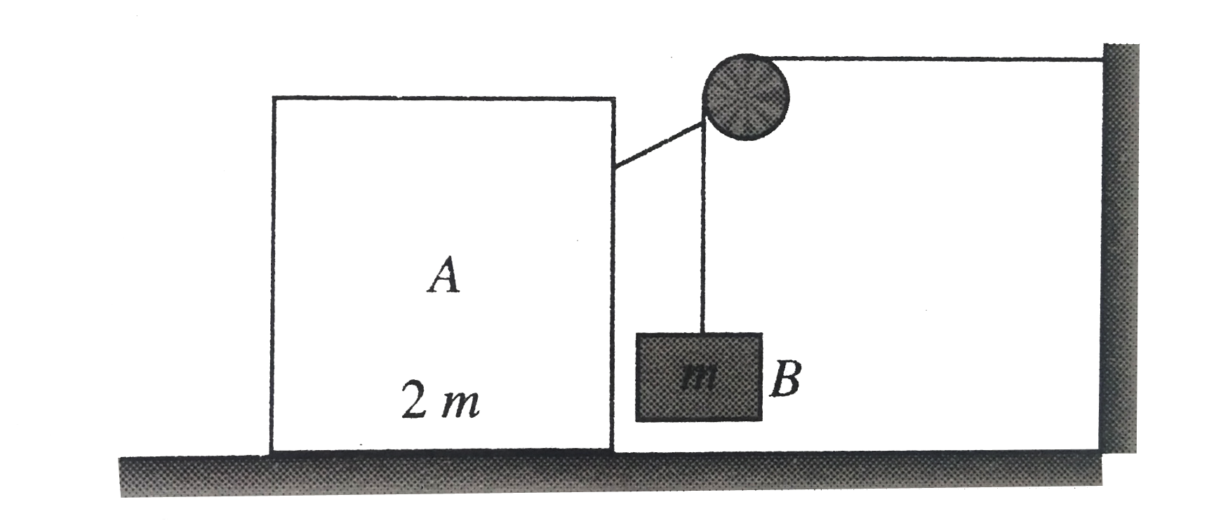
View SolutionIn the system shown all the surfaces are frictionless while pulley and string are massless. The mass of block A is 2m and that of block B is m. The acceleration of block B immediately after system is released from rest is
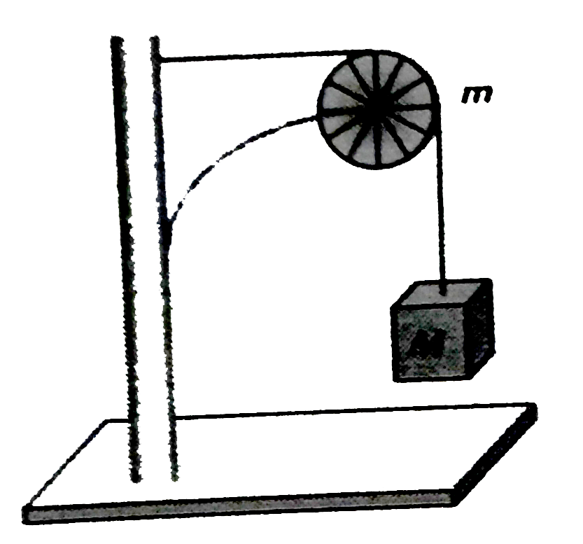
View SolutionA string of negligible mass going over a clamped pulley of mass m supports a block of mass M as shown in the figure. The force on the pulley by the clamp is given by
View Solution
