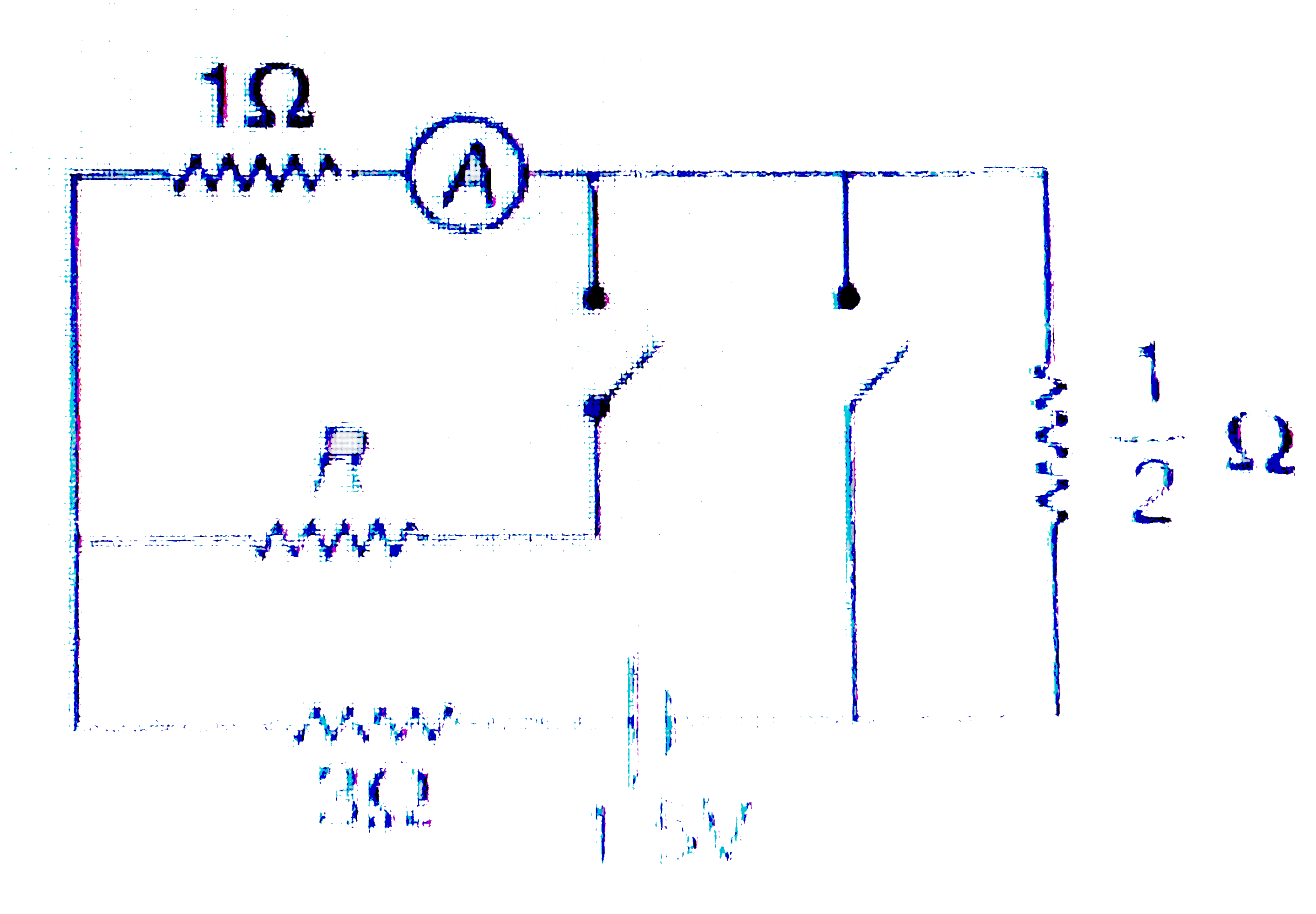
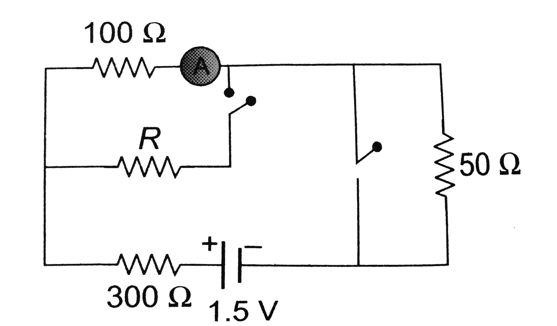
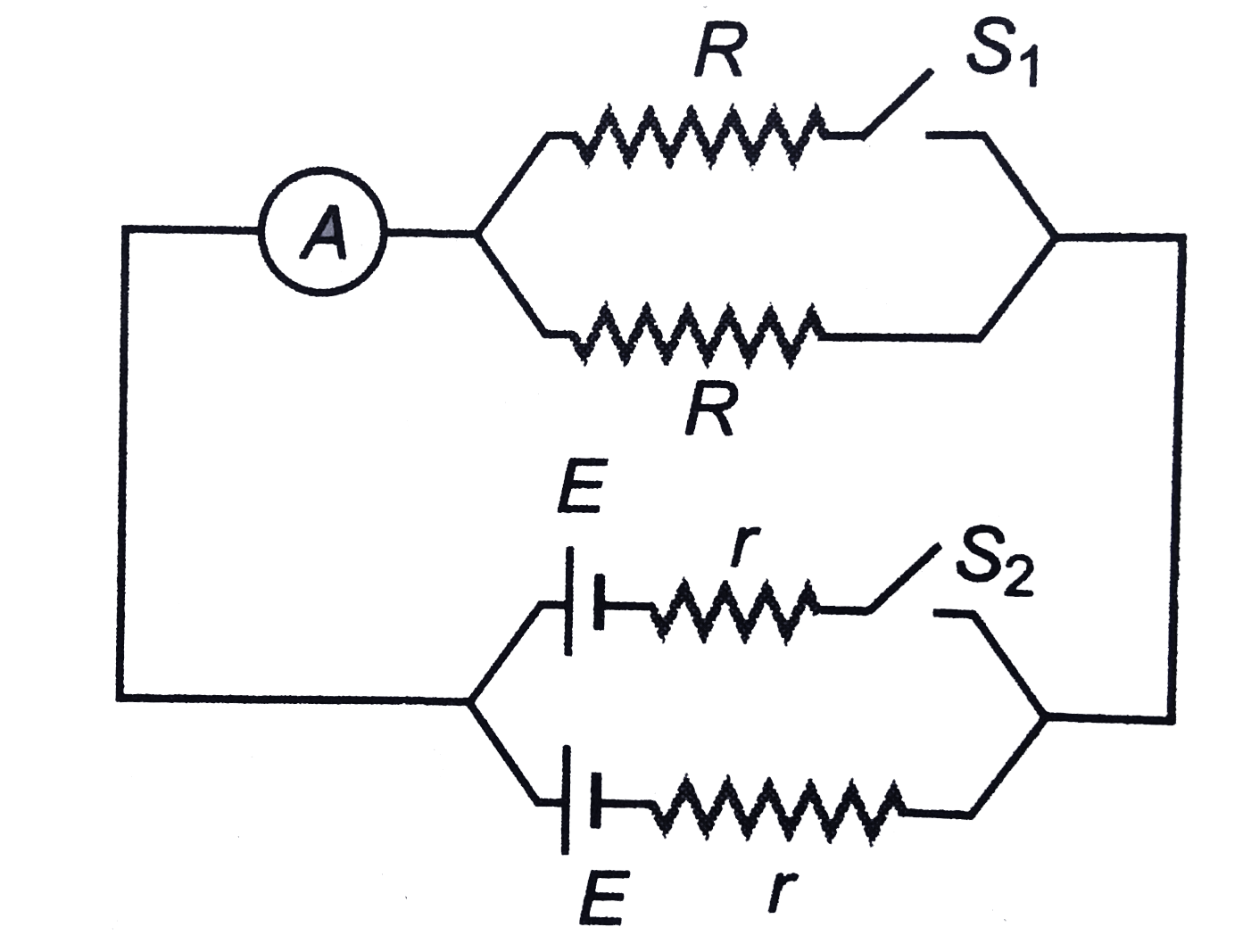
In the circuit shown in figure the reading of ammeter is the same with both switches open as with both closed. Then find the resistance R. (ammeter is ideal).
Video Solution
Text Solution
The correct Answer is:600Ω
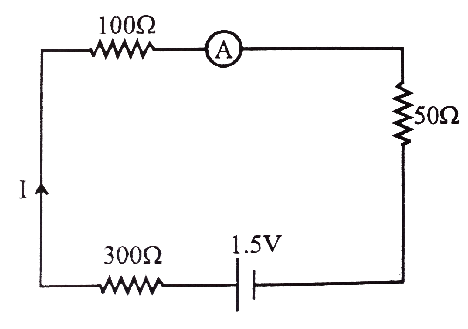
I=1.5450=1300 Amp...(1)
When both switch are closed
I100Ω=1.5100R100+R+300×R100+R....(2)
from (1) and (2)

6600Ω
|
Similar Questions
Knowledge Check
In the circuit shown in figure, reading of ammeter will
 Ashows no deflection if S1 is closedBdecrease if S2 is closedCincrease if S2 is closedDdecrease if S2 is closed
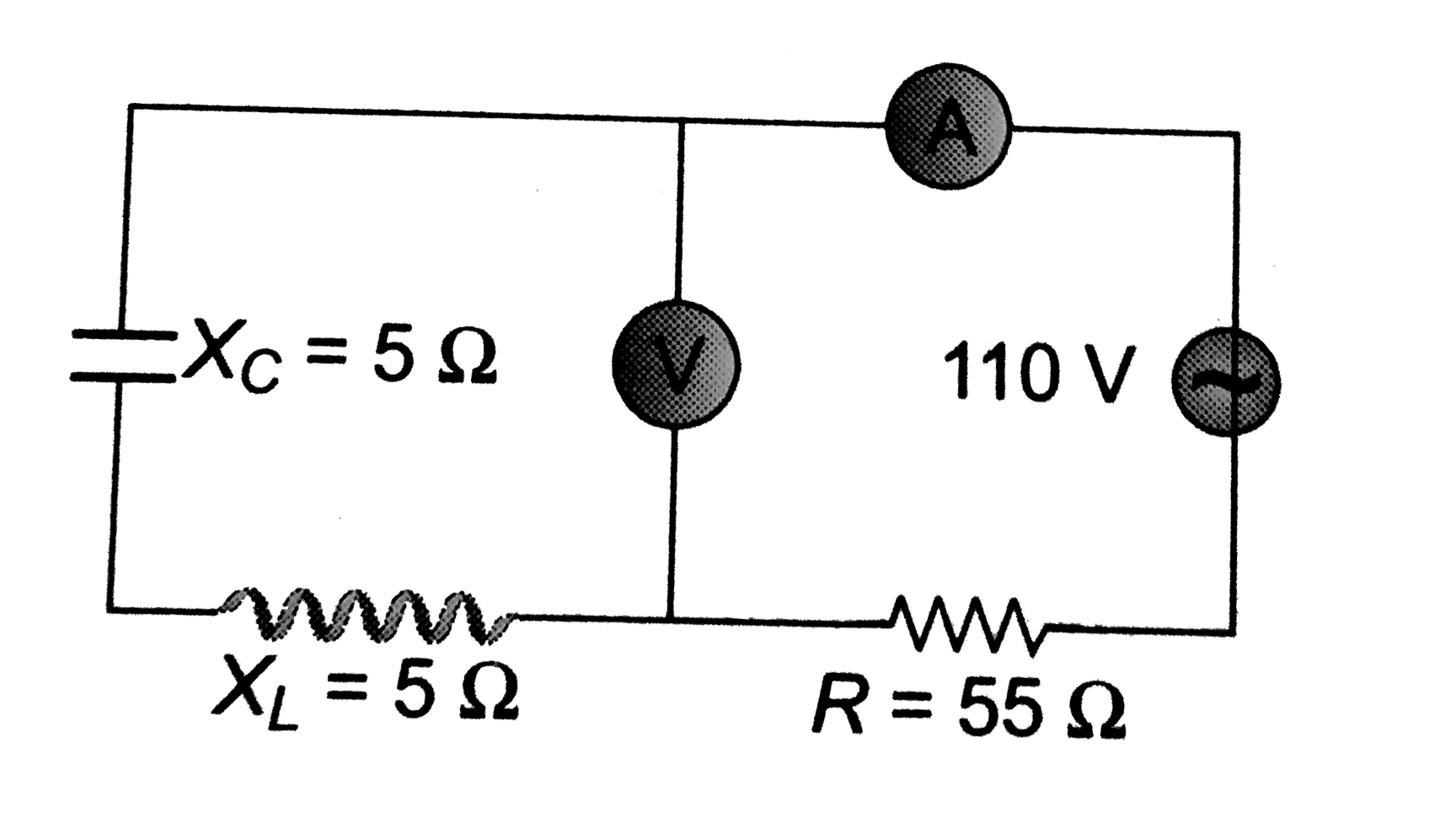
In the circuit shown, the reading of ammeter is:
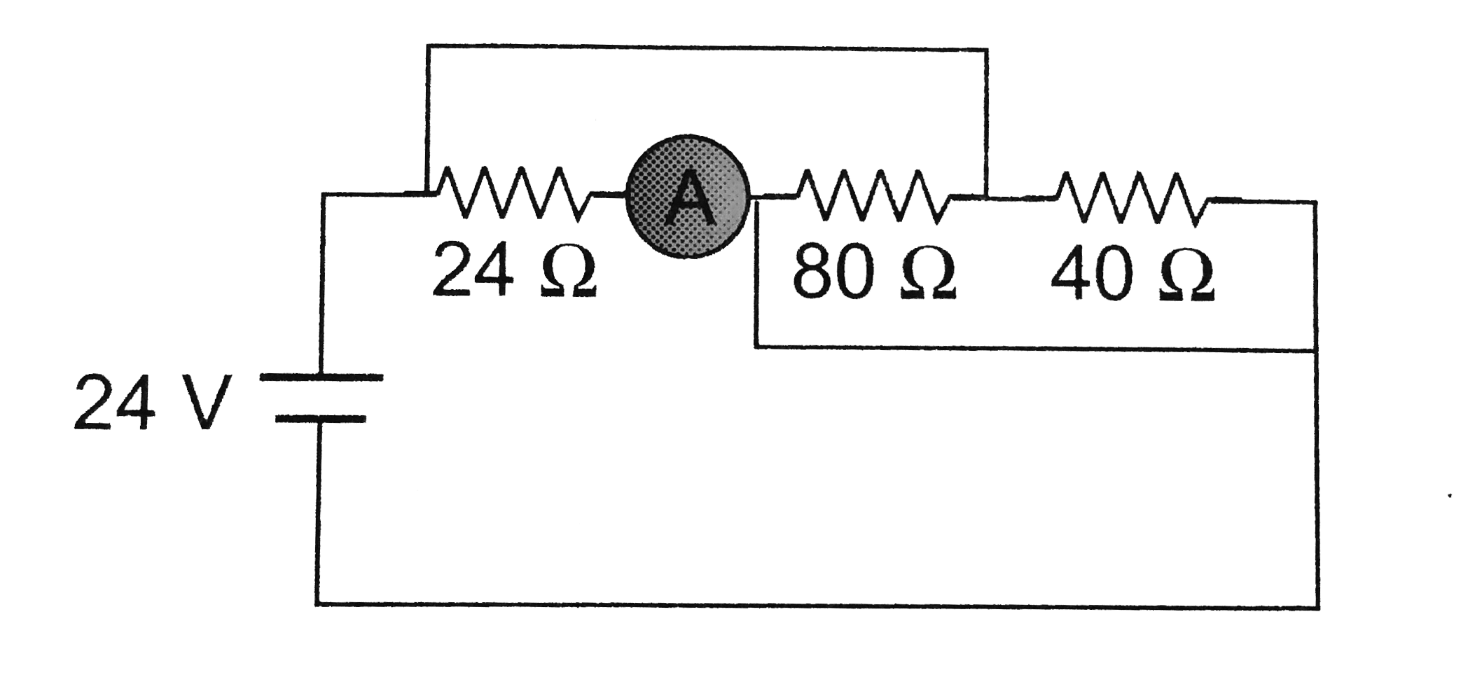 A0.2AB0.6AC2AD1A
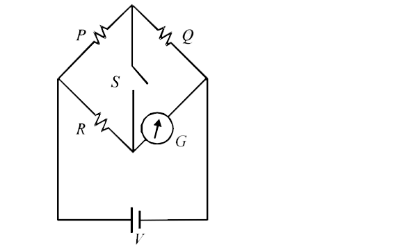
In the circuit shown P≠R the reading of galvonometer is same switch S open or closed. Then
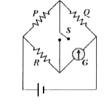 AIR=IGBIP=IGCIQ=IGDIQ=IS
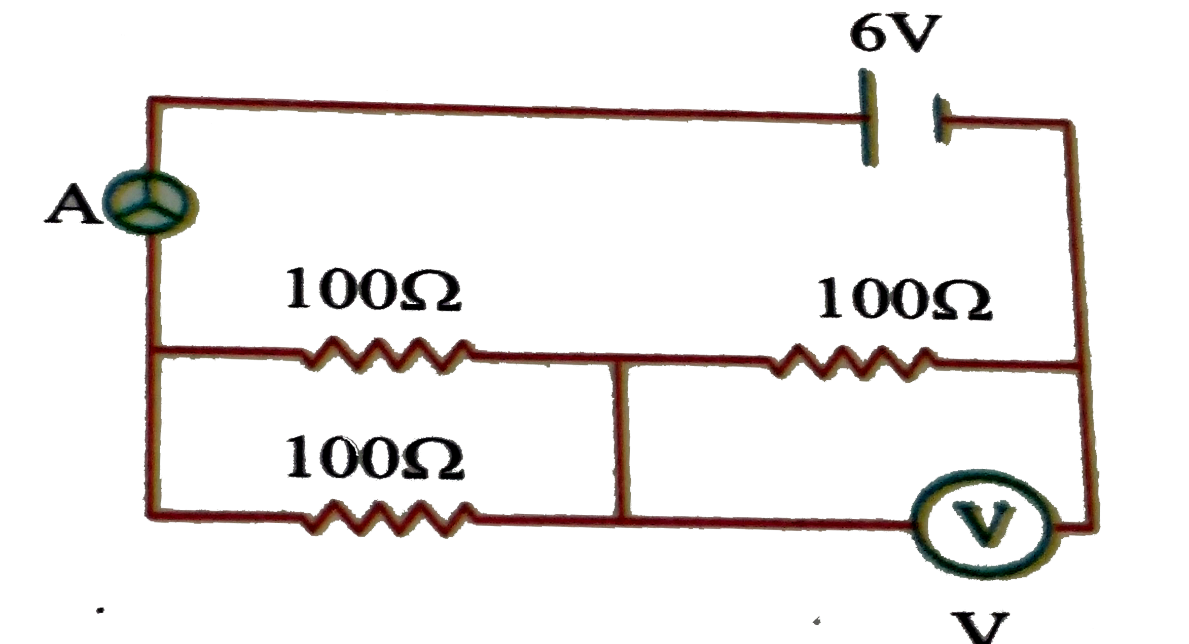
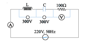
In the circuit shown, the reading of the voltmeter and the ammeter are
View SolutionIn the circuit P≠R, the reading of the galvanometer is same with switch S open or closed. Then
View SolutionThe reading of ammeter in the circuit shown will be
View SolutionIn the circuit shown, the reading of the ammeter if diode is not ideal, will be

View SolutionIn the circuit shown in figure, what will be the readings of voltmeter and ammeter?
View Solution

