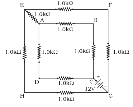
In the given circuit (as shown in fig. 5.319).
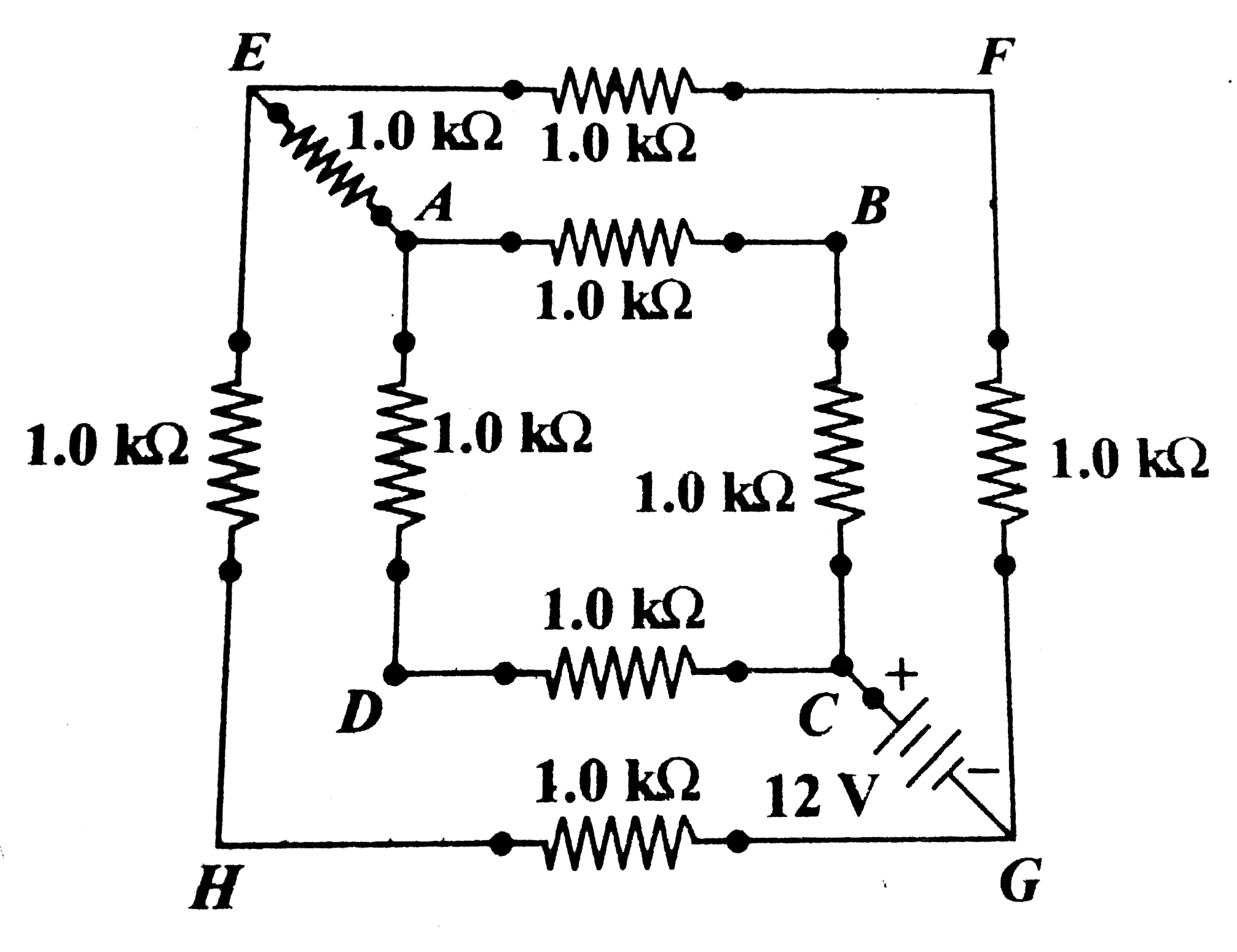
the equivalent resistance between C and G is 3Kω
the current provided by the source is 4 mA
the current provided by the source is 8mA
voltage across points G and E is 4V
The correct Answer is:A, B, D
The circuit can be redrawn as shown in the figure.
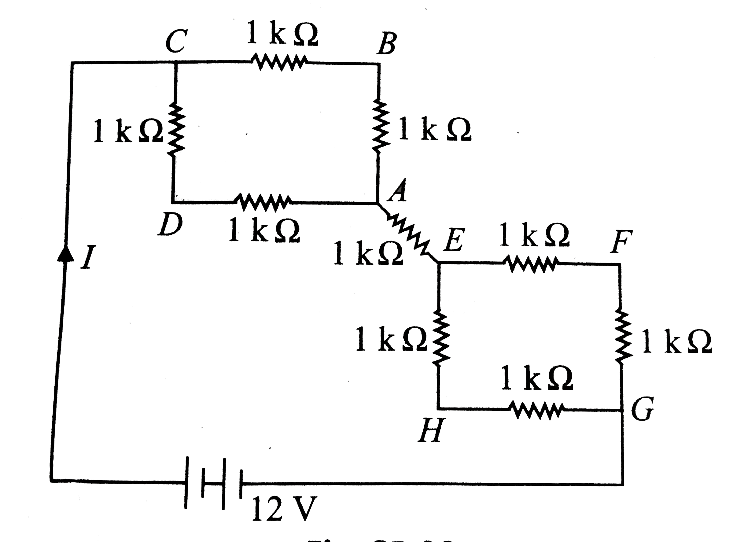
Req=3kΩ,I=123×103=4mA
VE−VG=I(1kΩ)=4×10−3×1x103=4V
Topper's Solved these Questions
- ELECTRIC CURRENT AND CIRCUITBOOK - CENGAGE PHYSICSCHAPTER - ELECTRIC CURRENT AND CIRCUITEXERCISE - Comprehension
35 Videos
- ELECTRIC CURRENT AND CIRCUITBOOK - CENGAGE PHYSICSCHAPTER - ELECTRIC CURRENT AND CIRCUITEXERCISE - Interger
8 Videos
- ELECTRIC CURRENT AND CIRCUITBOOK - CENGAGE PHYSICSCHAPTER - ELECTRIC CURRENT AND CIRCUITEXERCISE - Single Correct
72 Videos
- ELECTRIC CURRENT & CIRCUITSBOOK - CENGAGE PHYSICSCHAPTER - ELECTRIC CURRENT & CIRCUITSEXERCISE - Kirchhoff s law and simple circuits
15 Videos
- ELECTRIC FLUX AND GAUSS LAWBOOK - CENGAGE PHYSICSCHAPTER - ELECTRIC FLUX AND GAUSS LAWEXERCISE - MCQ s
38 Videos
Similar Questions
Knowledge Check
In the circuit shown in Fig. 7.45,
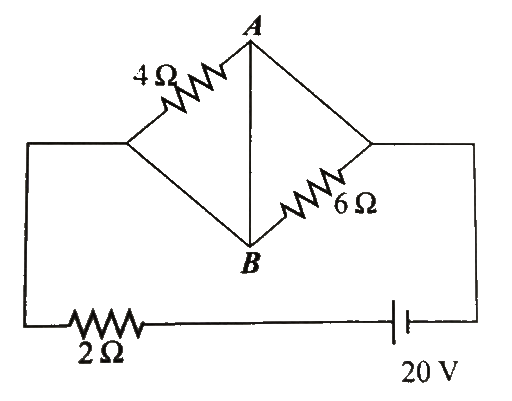 APower supplied by the battery is 200WBcurrent flowing in the circuit is 5ACPotential difference across the 4Ω resistance is equal to the potential difference across the 6Ω resistanceDcurrent in wire AB is zero
The potential difference between points A and B in the circuit shown in fig. 5.317 is 16V. Then
 Athe current through the 2Ω resistance is 3.5ABthe current through 4Ω resistance is 2.5ACthe current through 3Ω resistance is 1.5ADthe potential difference between the terminals of the 9V battery is 7V
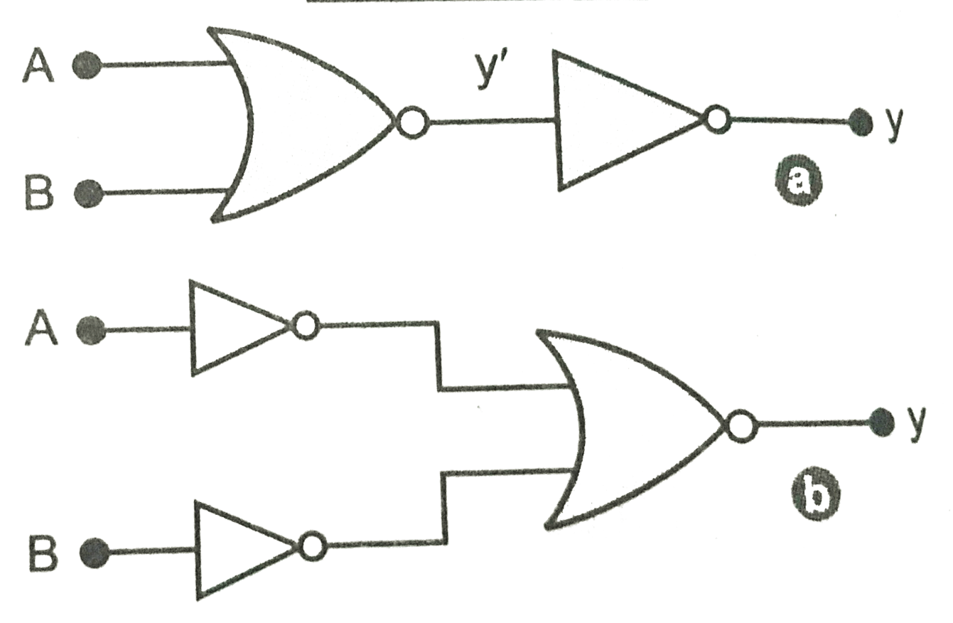
You are given two circuit as shown in Fig.and . Which consists of NAND gates. Identify the logic operation carried out by the two circuits.

View SolutionYou are given the two circuits as shown in Fig. and . Show that circuit acts as OR gate while the circuit acts as AND gate.
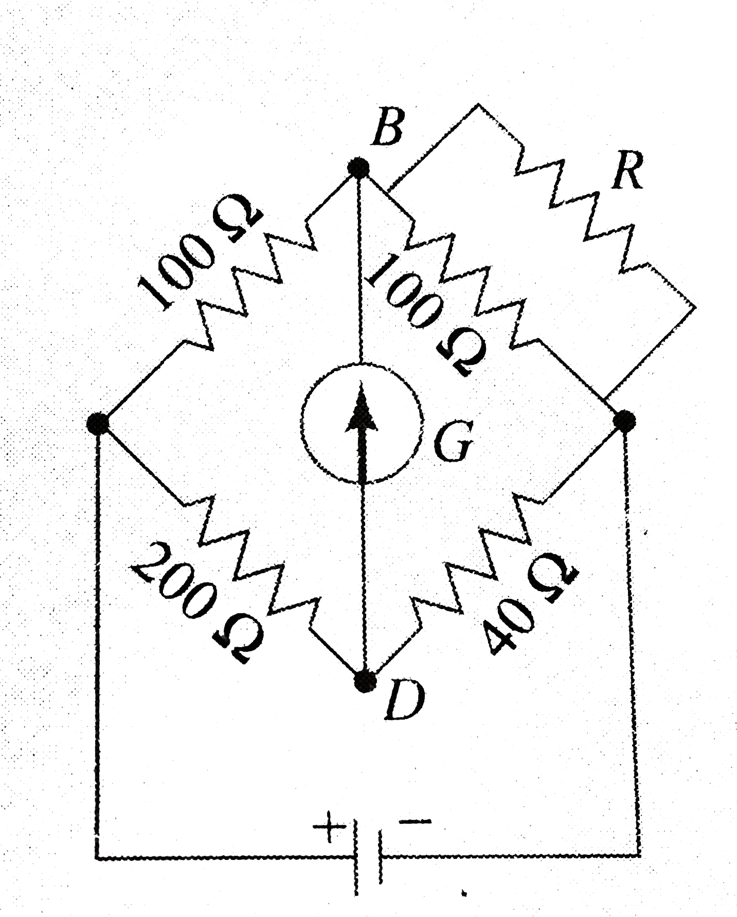
View SolutionFind the current in each resistor in the circuit as shown in fig.
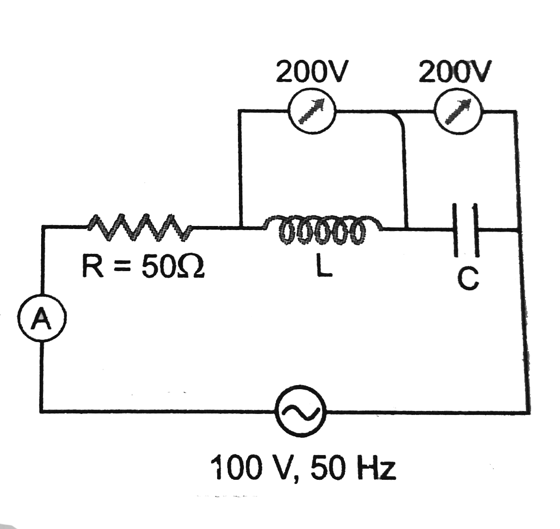
View SolutionIn the series RLC circuit as shown in Fig., what would be the ammeter reading in ampere ?
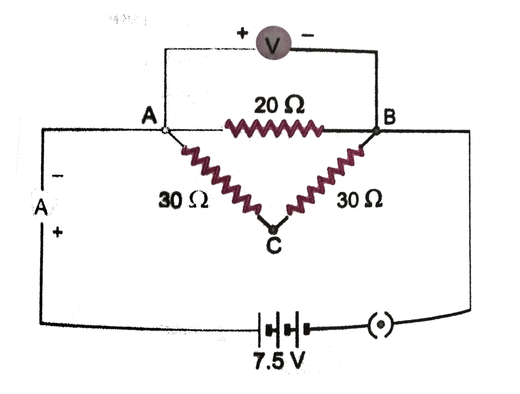
View SolutionIn the circuit shown in (fig. 3.51), find the current recorded by ammeter (A).
 .
.
View SolutionFor the given circuit shown in fig, to act as full wave rectifier :– a.c. input should be connected across ................. and ..................... the d.c. output would appear across ................ and .....................
View Solution

