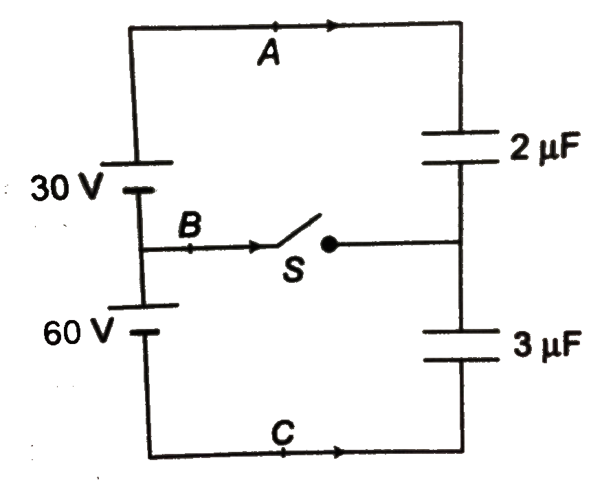
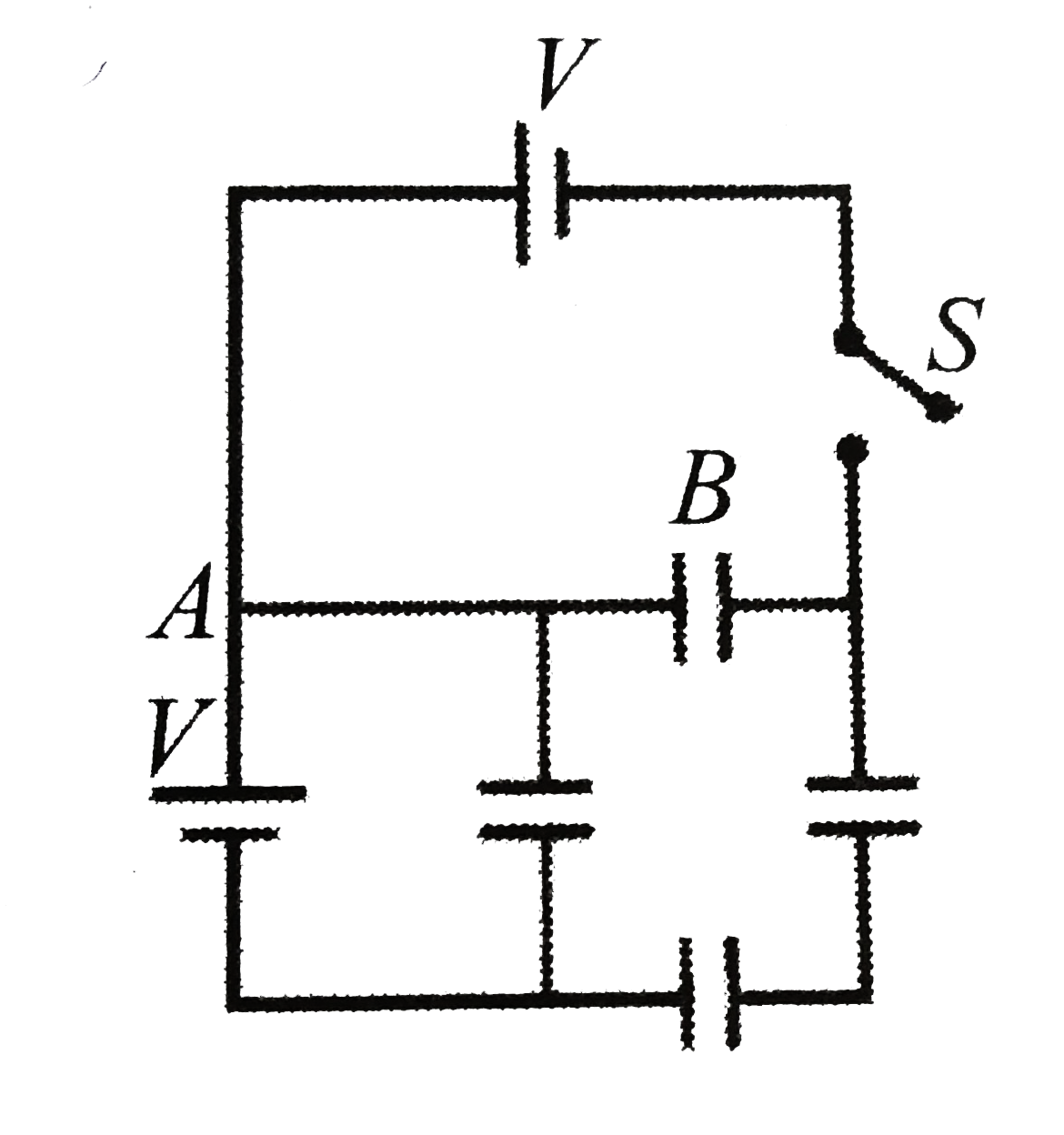
What charges will flow through and in the direction shown in the figure when swithc is closed?
, ,
, ,
, ,
, ,
The correct Answer is:A
Let us draw two figure and find the charge on both the capacitors before closing the switch and after closing the switch. 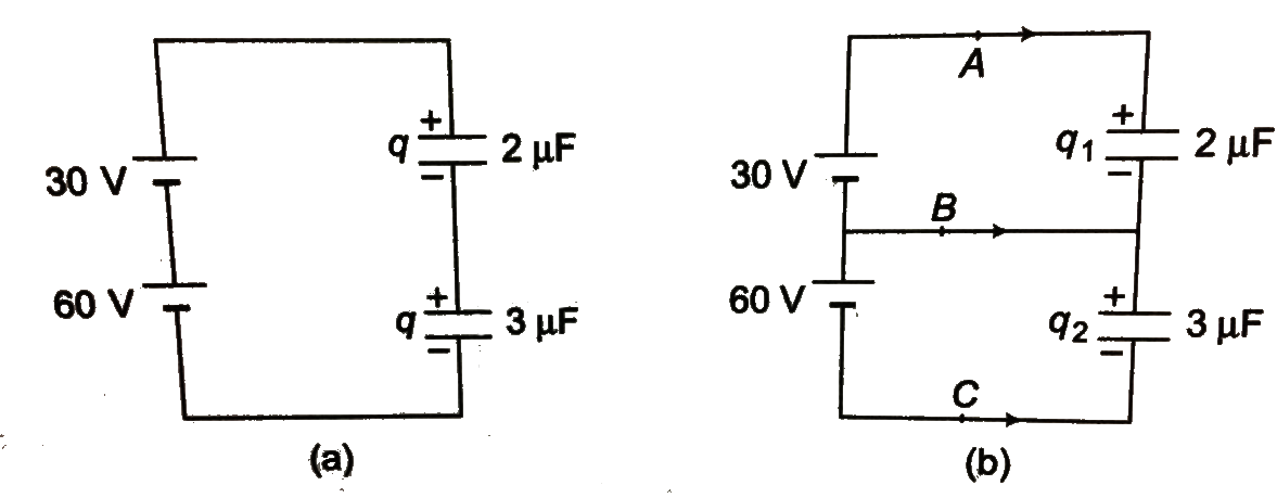
Refer fig a. when switch is open Both capacitors are in series. Hence, their equivalent capacitance is
therefore, charge on both capacitors will be same, Hence, using we get
Refer fig b. when switch is closed Let and be the charges ( on two capacitors. Then applying second law in upper and lower loops, we have
or
or
Charges and can be calculated alternatively by seeing that upper plate of capcior is connected with positive terminal of battery. THereforwe, they are at the same potential. Similarly, thelower plate of this capacitor is at the same potential as that of the negative terminal of battery. So, we can say that across capacitor is also .
Similarly across capacitor is same as that between battery. hence,
Now let charge flows from in the direction shown. This charge goes to the upper plate of capacitor. initialy, it had charge and final charge on it is Hence
or
Similarly charge goes to the upper plate of capacitor and lower plate of capacitor. INitially both the plates had a chaerge or zero. And finally they have a charge
Hence
Charge goes to the lower plate of capacitor. Initially, it had a charge and finally Hence ltbr
so, the charges will flow as shown below

Topper's Solved these Questions
- CAPACITORSBOOK - DC PANDEYCHAPTER - CAPACITORSEXERCISE - Exercise
155 Videos
- CAPACITORSBOOK - DC PANDEYCHAPTER - CAPACITORSEXERCISE - OBJECTIVE_TYPE
1 Videos
- ATOMSBOOK - DC PANDEYCHAPTER - ATOMSEXERCISE - MEDICAL ENTRANCES GALLERY
42 Videos
- COMMUNICATION SYSTEMBOOK - DC PANDEYCHAPTER - COMMUNICATION SYSTEMEXERCISE - Subjective
11 Videos
Similar Questions
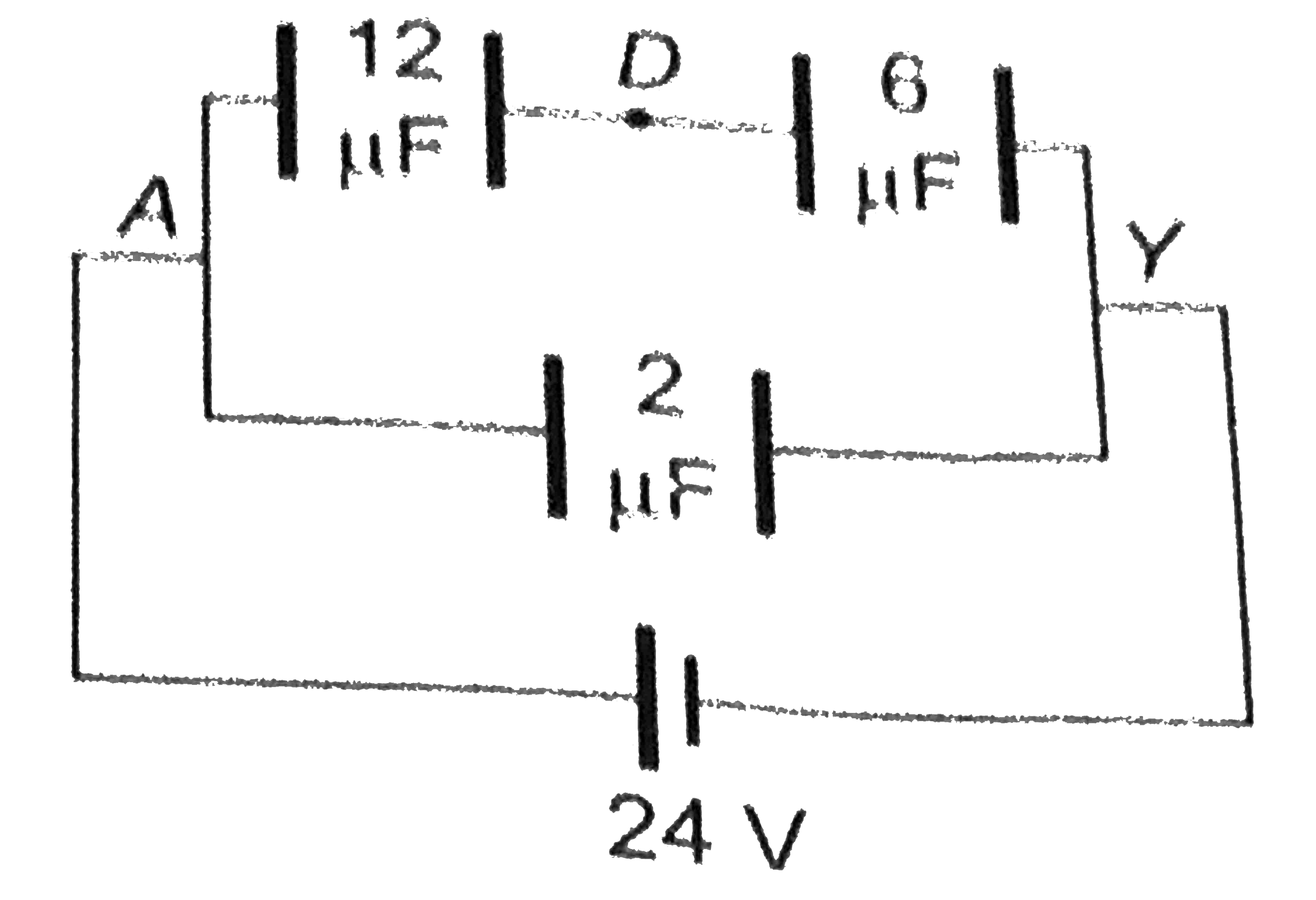
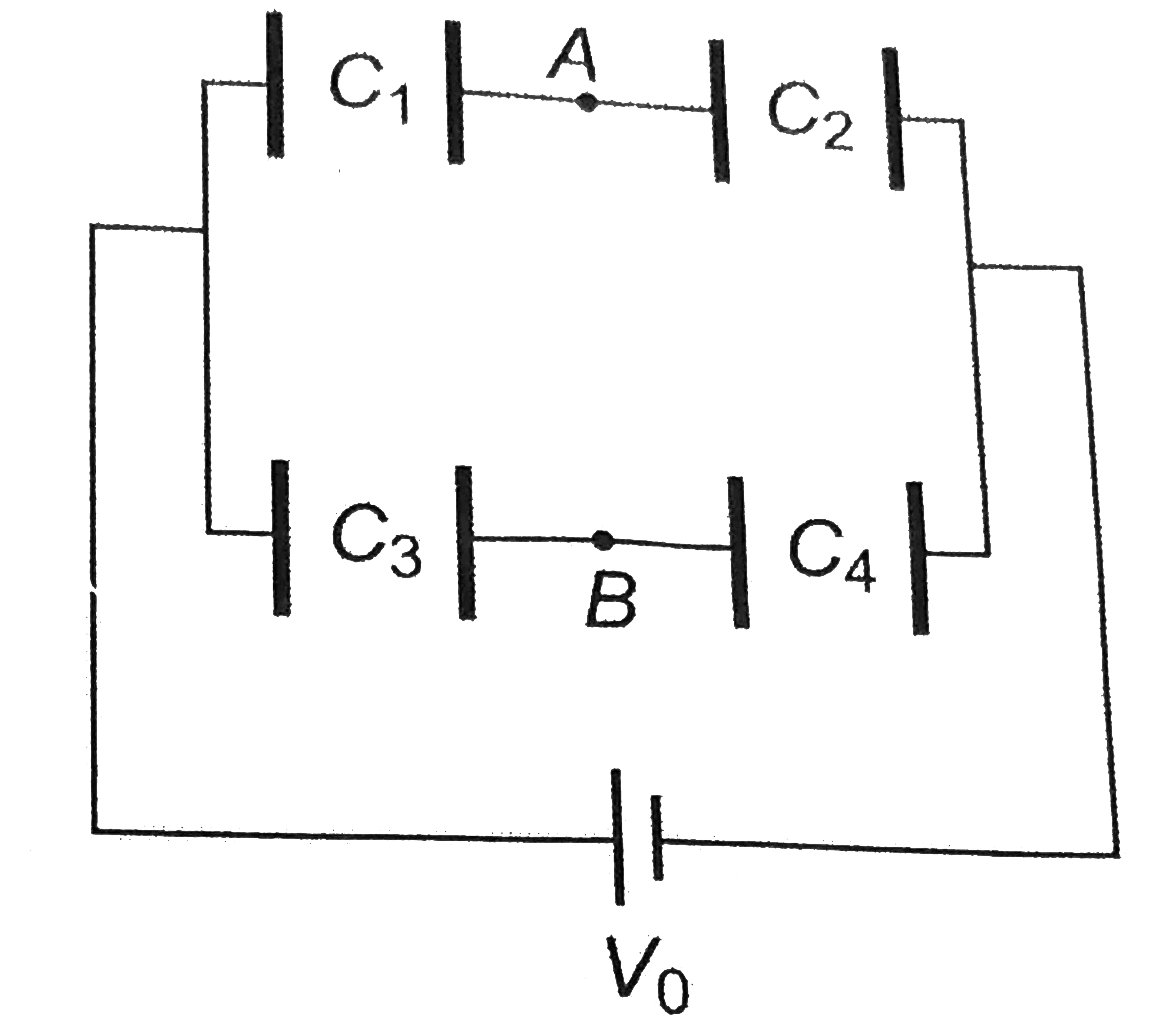
(a) Taking the potential at the point B to be zero, find the potential of point D.
(b) Find VA−VB. Under what condition is it equal to zero.
(c) Consider the situation as shown in diagram. How much charge will flow through cell if the switch S is closed?
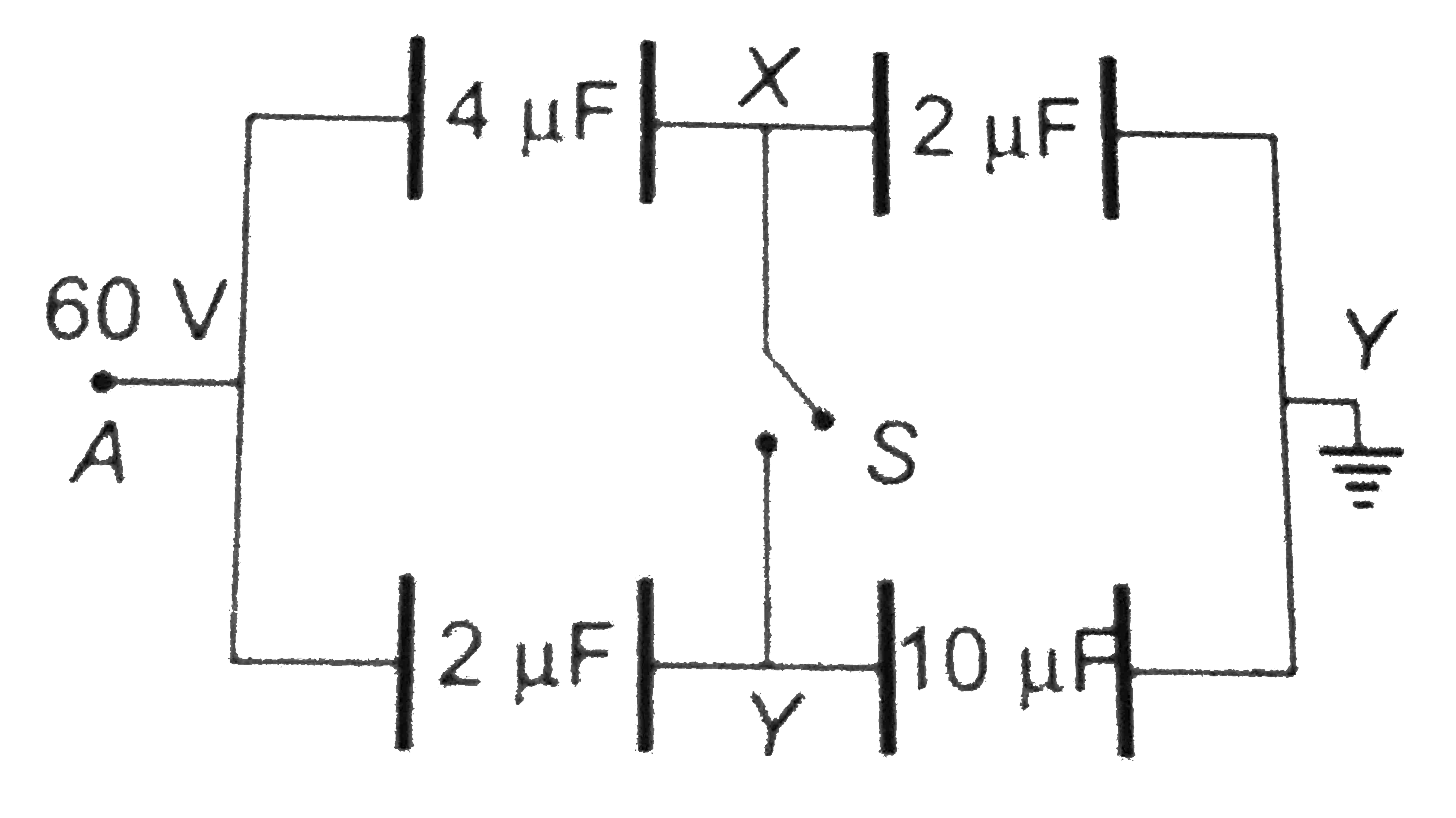
(d) In the circuit shown in the figure, calculate
(i) Potential difference between the points X and Y.
(ii) Potential of the point X when switch S is closed.
(iii) Charge flown through the switch when it was closed.

View SolutionDetermine the current through the battery in the circuit shown in figure.
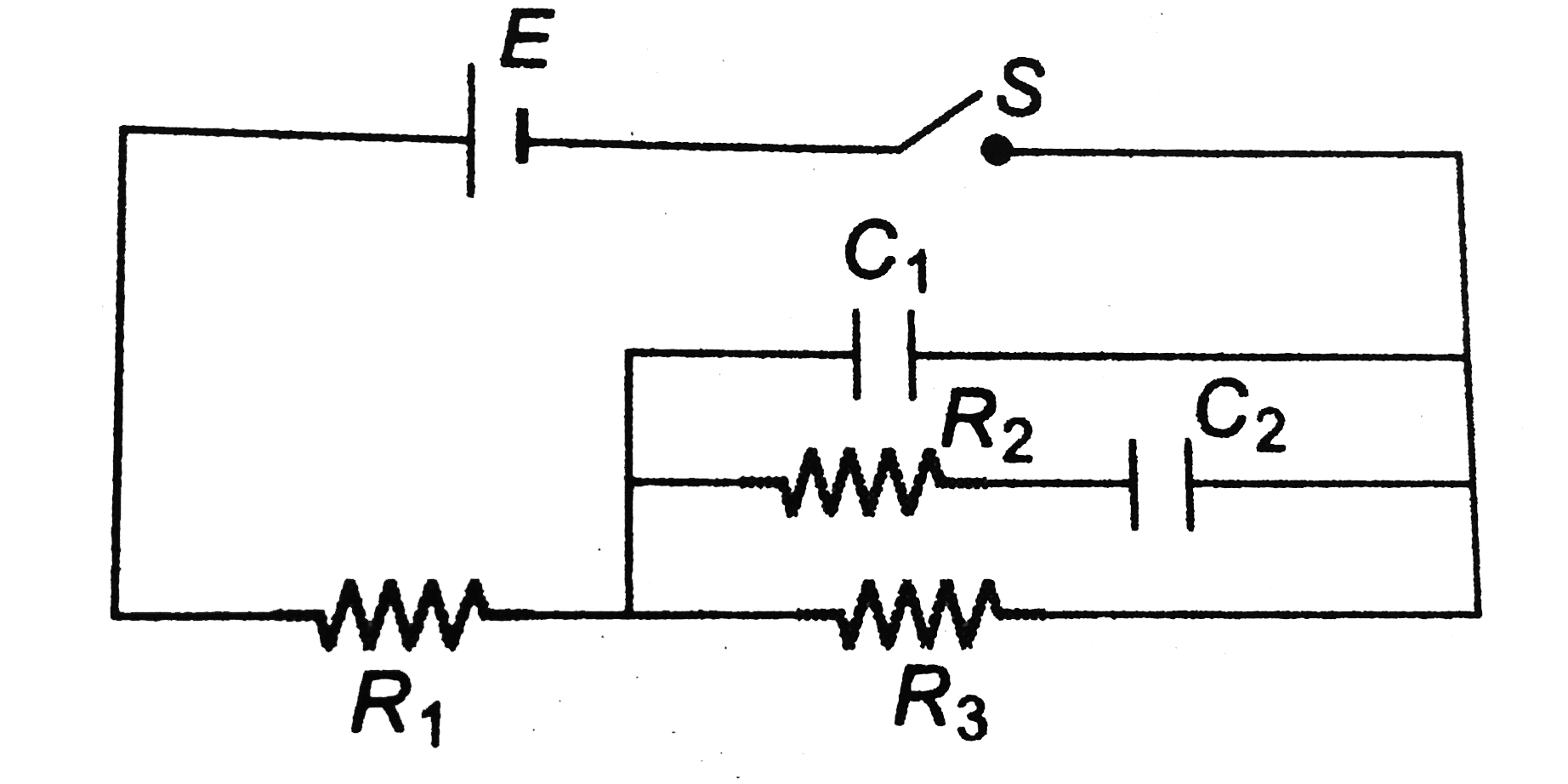
(a) immediately after the switch S is closed
(b) after a long time.
View Solution
Knowledge Check
In the figure shown the current flowing through 2R is:
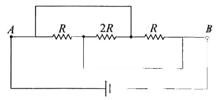 Afrom left to rightBfrom right to leftCno currentDnone of these
Two capacitors A and B are connected in series with a battery as shown in the figure. When the switch S is closed and the two capacitors get charged fully, then
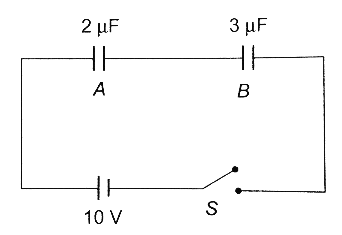 AThe potential difference across the plates of A is 4V and across the plates of B is 6VBThe potential difference across the plates of A is 6V and across the plates of B is 4VCThe ratio of electrical energies stored in A and B is 2:3DThe ratio of charges on A and B is 3:2
Find the charge that will flow through the wire A and B if the switch S is closed. The capacitance of each capacitance of each capacitor shown in the figure is C.
 ACVBCV/3CzeroD2CV/3
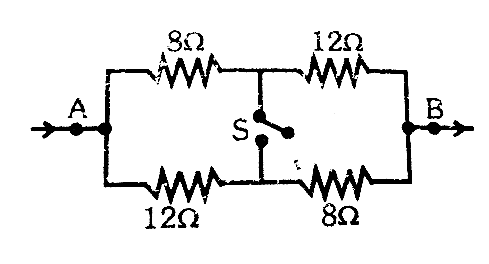
Calculate the equivalent resistance of the resistance network between the points A and B as shown in the figure, when switch S is closed.
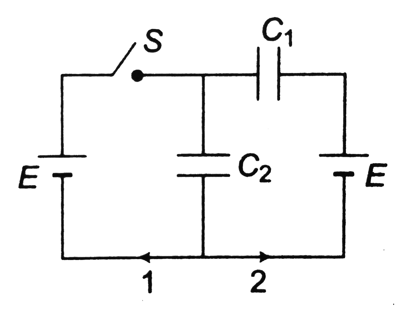
View SolutionIn the given circuit diagram, find the charges which flow through directions 1 and 2 when switch S is closed.
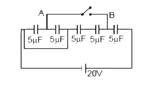
View SolutionFind the charge which flows from point A to B, when switch is closed
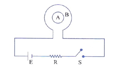
View SolutionA closed circular wire loop A lies in the plane D larger loop B which is connected to the battery as shown in figure. What is the direction of current induced in the loop A when the switch S is closed?
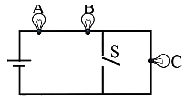
View SolutionA circuit consists of three identical lamps connected to a battery as shown in the figure. When the switch S is closed then the intensities of lamps A and B
View Solution
