In the circuit shown all the ammeters are ideal.
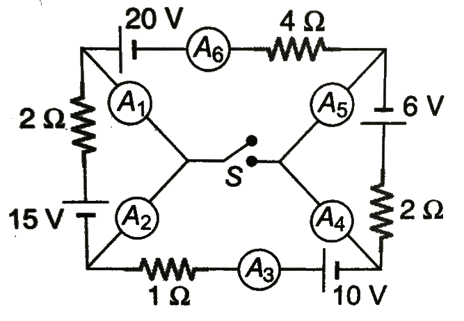
(a), If the switch S is open, find the reading of all ammeters and the potential difference across the switch.
(b) If the switch S is closed, find the current through all ammeters and the switch also.
Video Solution
Text Solution
The correct Answer is:A, B
NA
|
Topper's Solved these Questions
- CURRENT ELECTRICITYBOOK - DC PANDEYCHAPTER - CURRENT ELECTRICITYEXERCISE - Example
61 Videos
- CURRENT ELECTRICITYBOOK - DC PANDEYCHAPTER - CURRENT ELECTRICITYEXERCISE - Check point
70 Videos
- CURRENT ELECTRICITYBOOK - DC PANDEYCHAPTER - CURRENT ELECTRICITYEXERCISE - Level 2 Comprehension Example Type
2 Videos
- COMMUNICATION SYSTEMBOOK - DC PANDEYCHAPTER - COMMUNICATION SYSTEMEXERCISE - Subjective
11 Videos
- ELECTROMAGNETIC INDUCTIONBOOK - DC PANDEYCHAPTER - ELECTROMAGNETIC INDUCTIONEXERCISE - Medical entrances gallery
25 Videos
Similar Questions
Knowledge Check
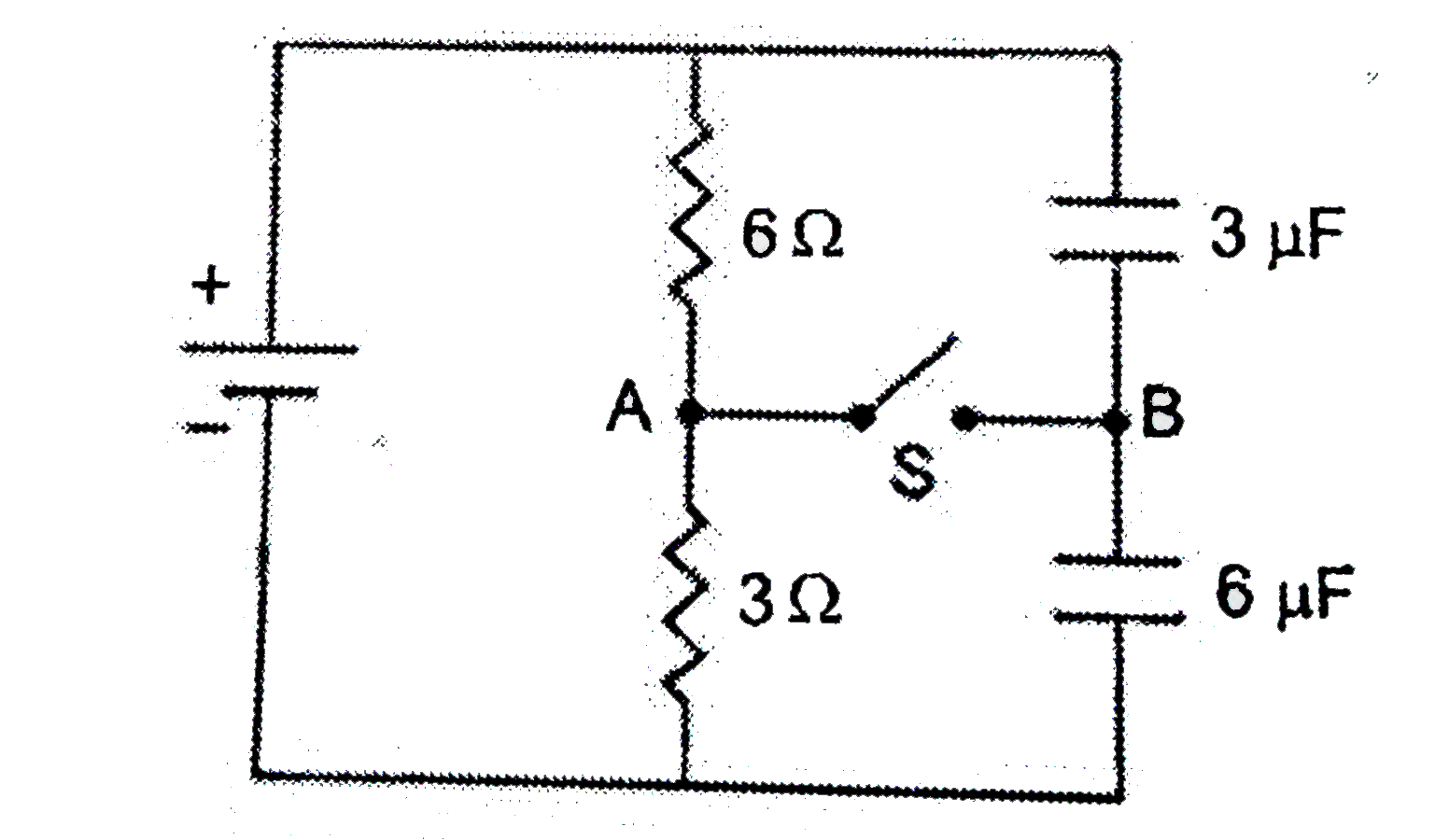
In the circuit shown above, when then switch S is closed,Ano charge flows through SBcharge flows from A to BCcharge flows from B to ADcharge flows initially from A to B and later from B to AIn the circuit in Fig. switch S1 was closed for a long time . At time t=0 the switch is opened.
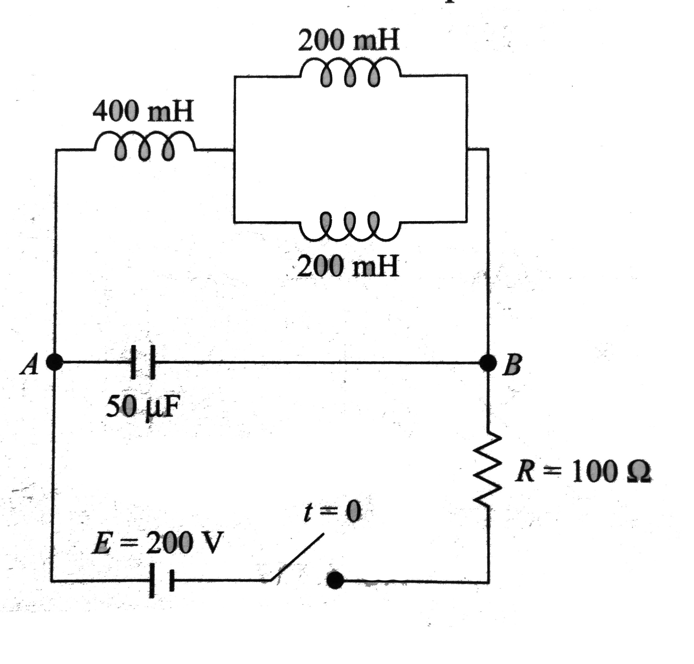
Find the maximum potentail difference across the plates of the capacitor after the switch is opened.A100VB200VC300VD400VIn the circuit shown, the reading of ammeter when switch S is open and when switch S is closed respectively are
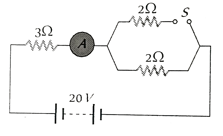 A3A and 4AB4A and 5AC5A and 6AD6A and 7A
In the circuit shown in fig, switch S was closed for long time. At time t-0, teh switch is opened again. The maximum potential difference across teh plates of the capacitor after the switch is opened is

View SolutionAs the switch S is closed in the circuit shown in figure, current passed through it is.
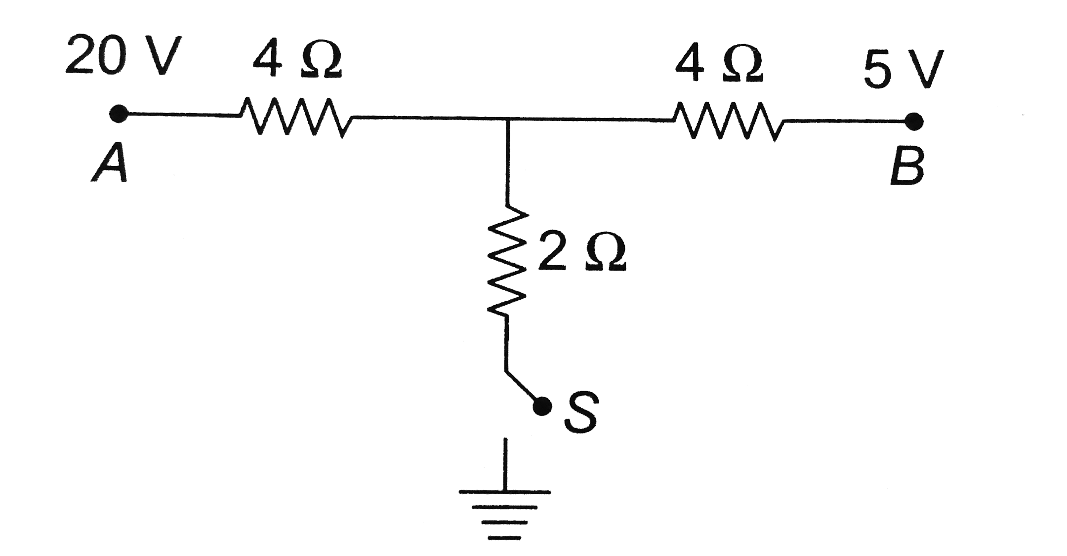
View SolutionWhen the switch S is closed in the given circuit, the current passed through it is

View SolutionIn the arrangement shown in , the switch S is find
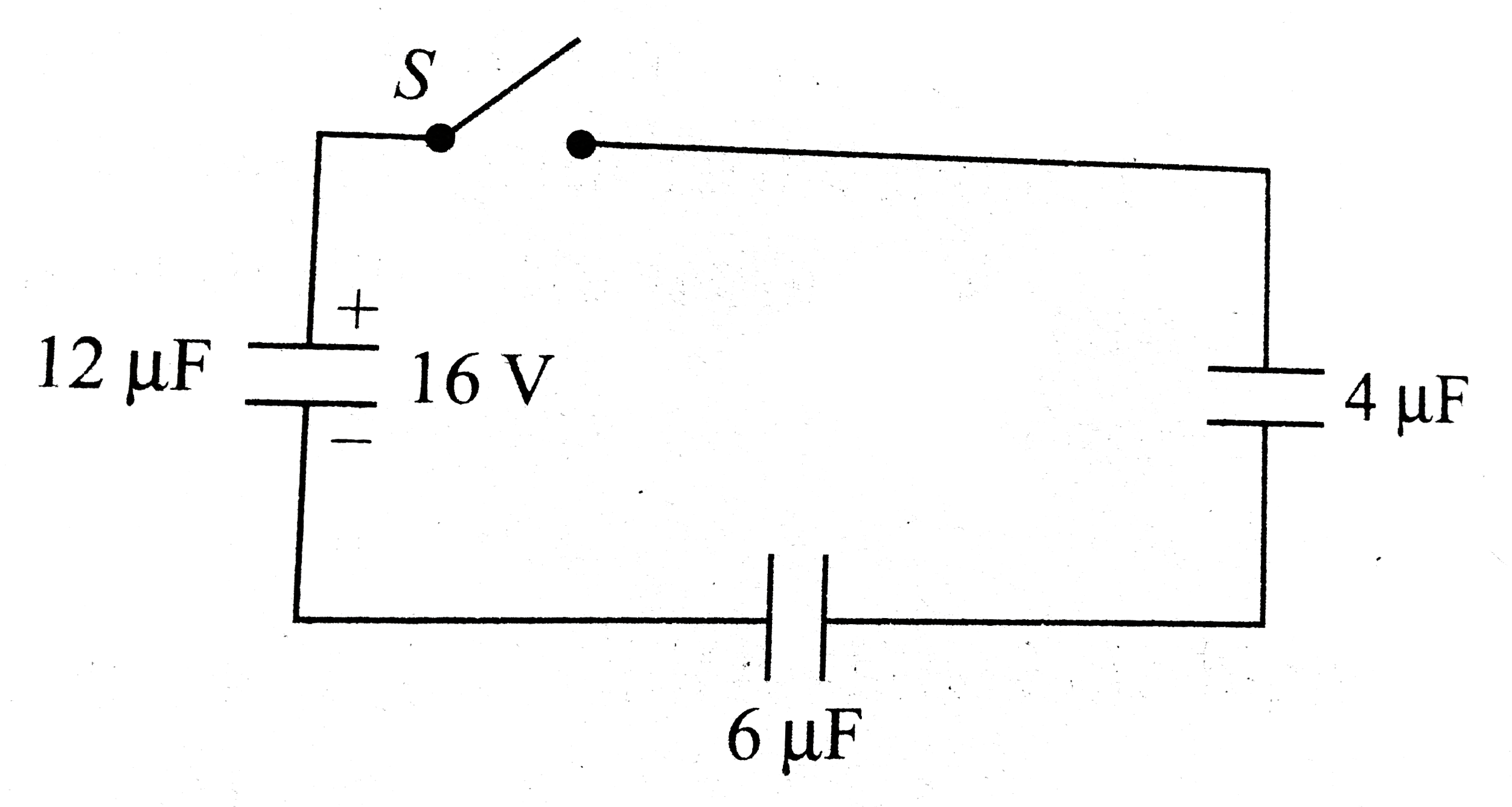 the final potential difference across the 4μF capacitor
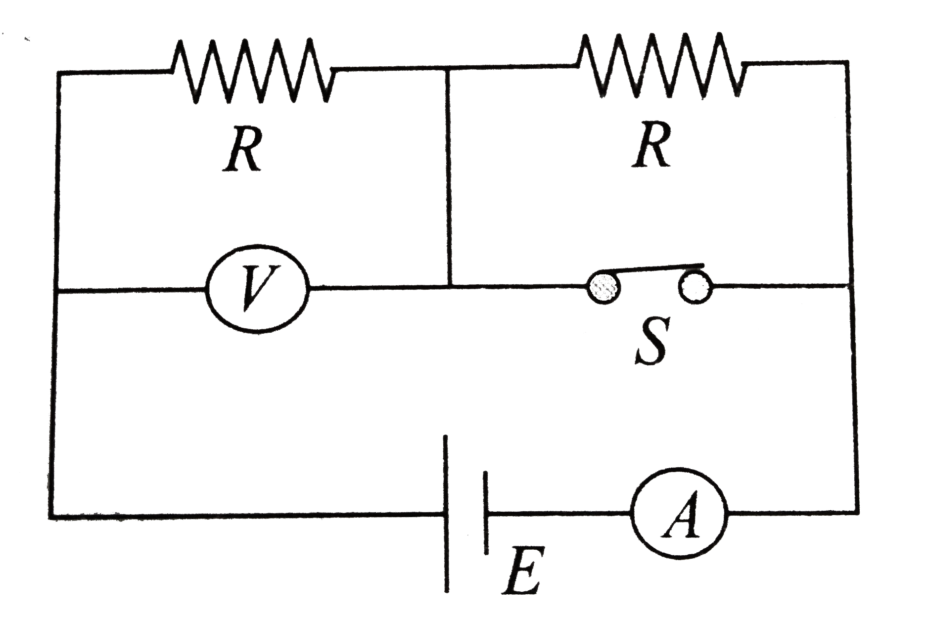
View SolutionIn the circuit shown, battery, ammeter , and voltmeter are ideal and the switch S is initially closed as shown. When switch S is opened
View Solution

