True and False from CENGAGE PHYSICS (ENGLISH) MISCELLANEOUS VOLUME 3 for Class 12
| Class 12 | PHYSICS |
| Chapter | MISCELLANEOUS VOLUME 3 |
| CENGAGE PHYSICS (ENGLISH) | True and False |
| Medium | English |
| Academic Year | 2023-2024 |
Question 15
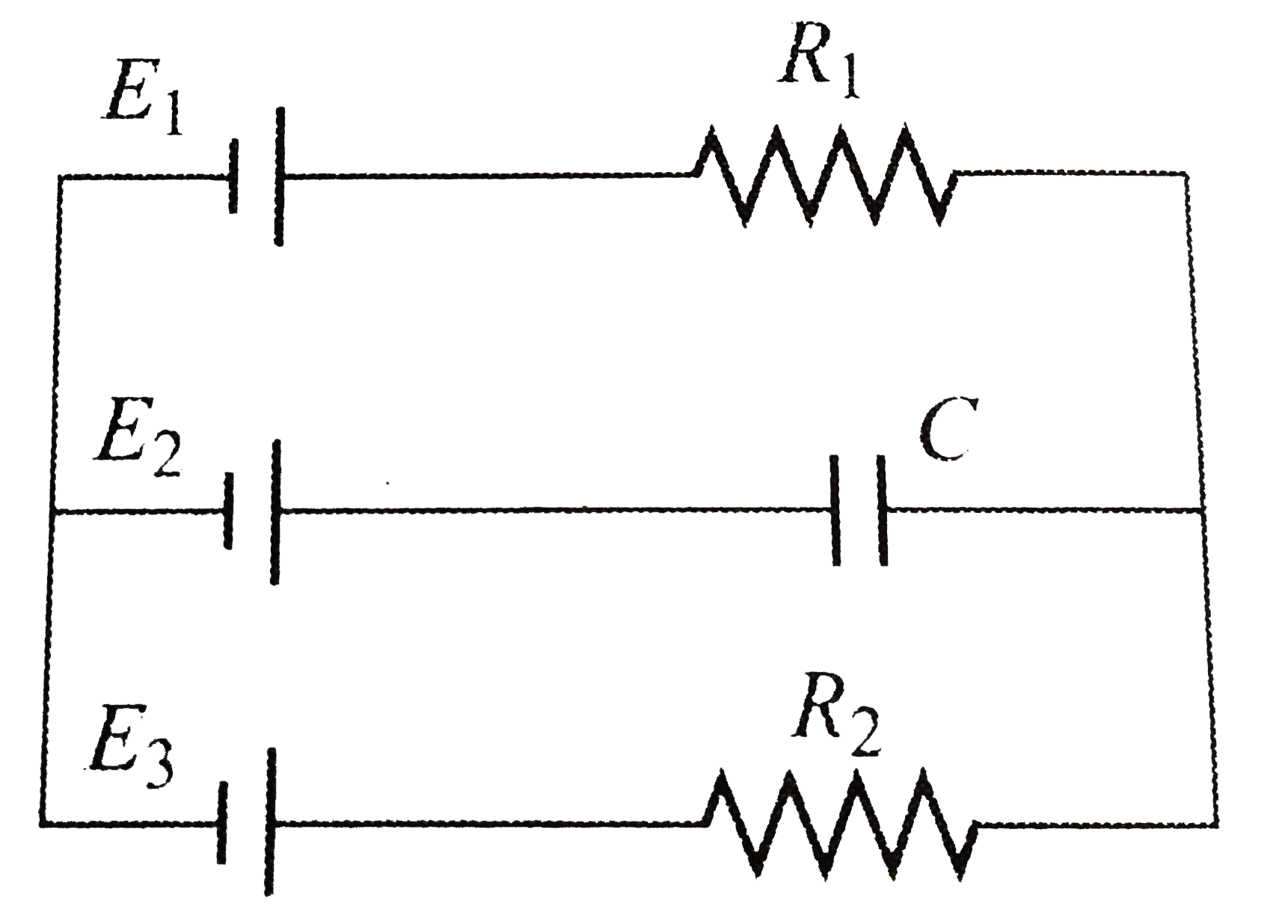
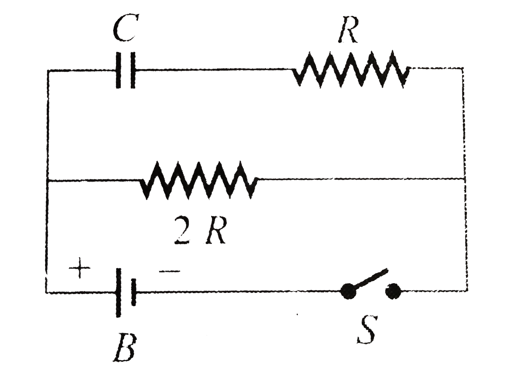
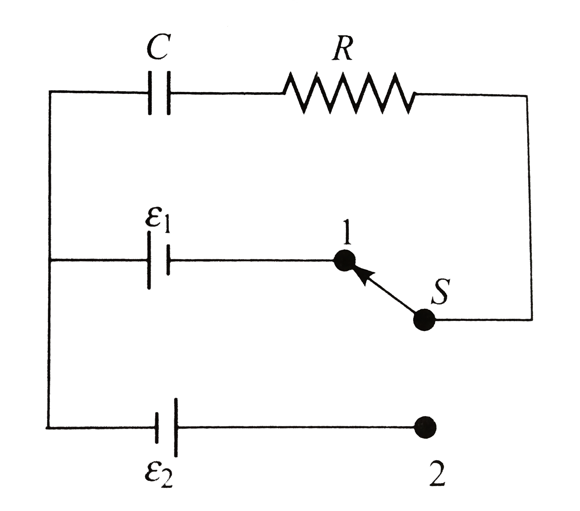
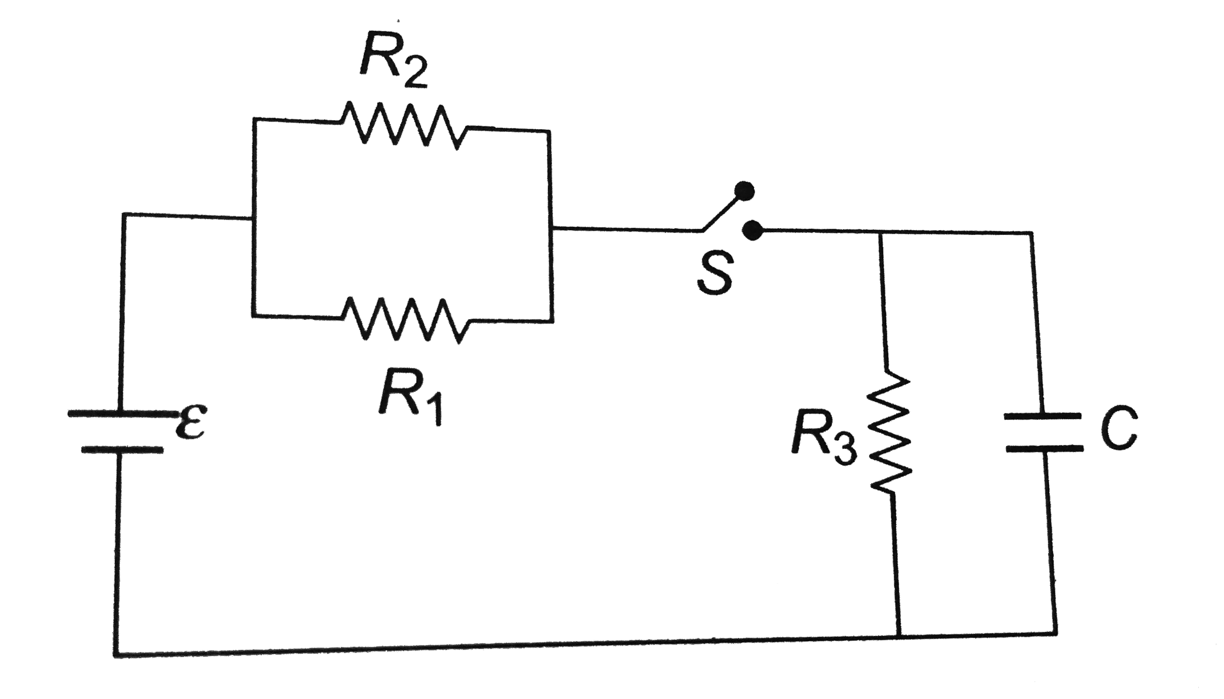
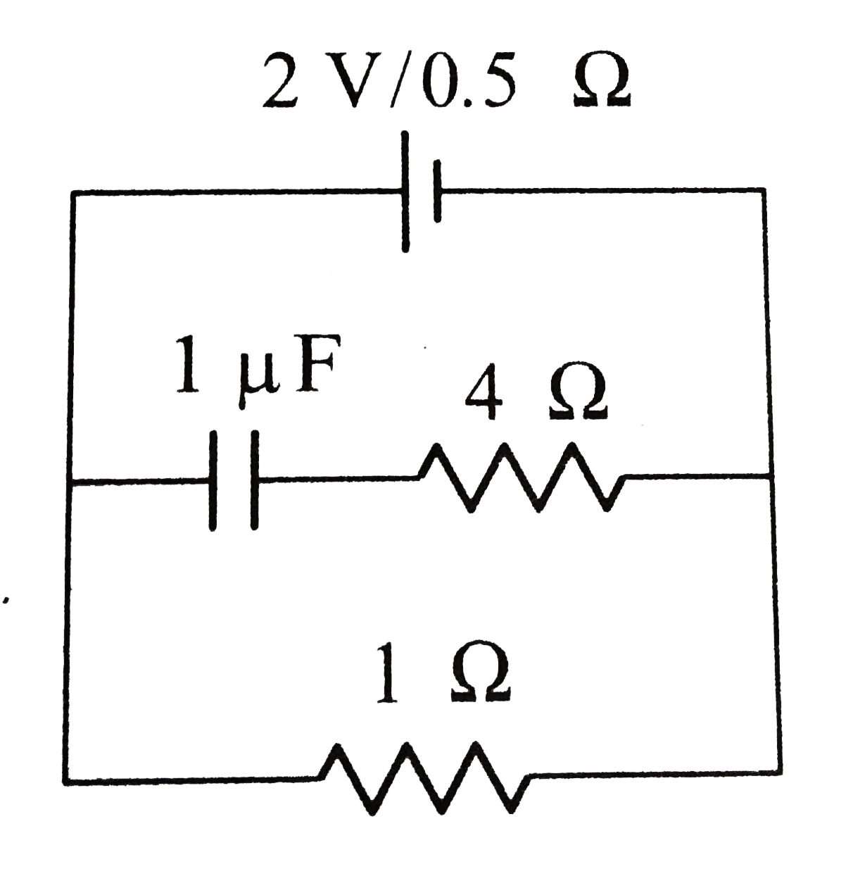
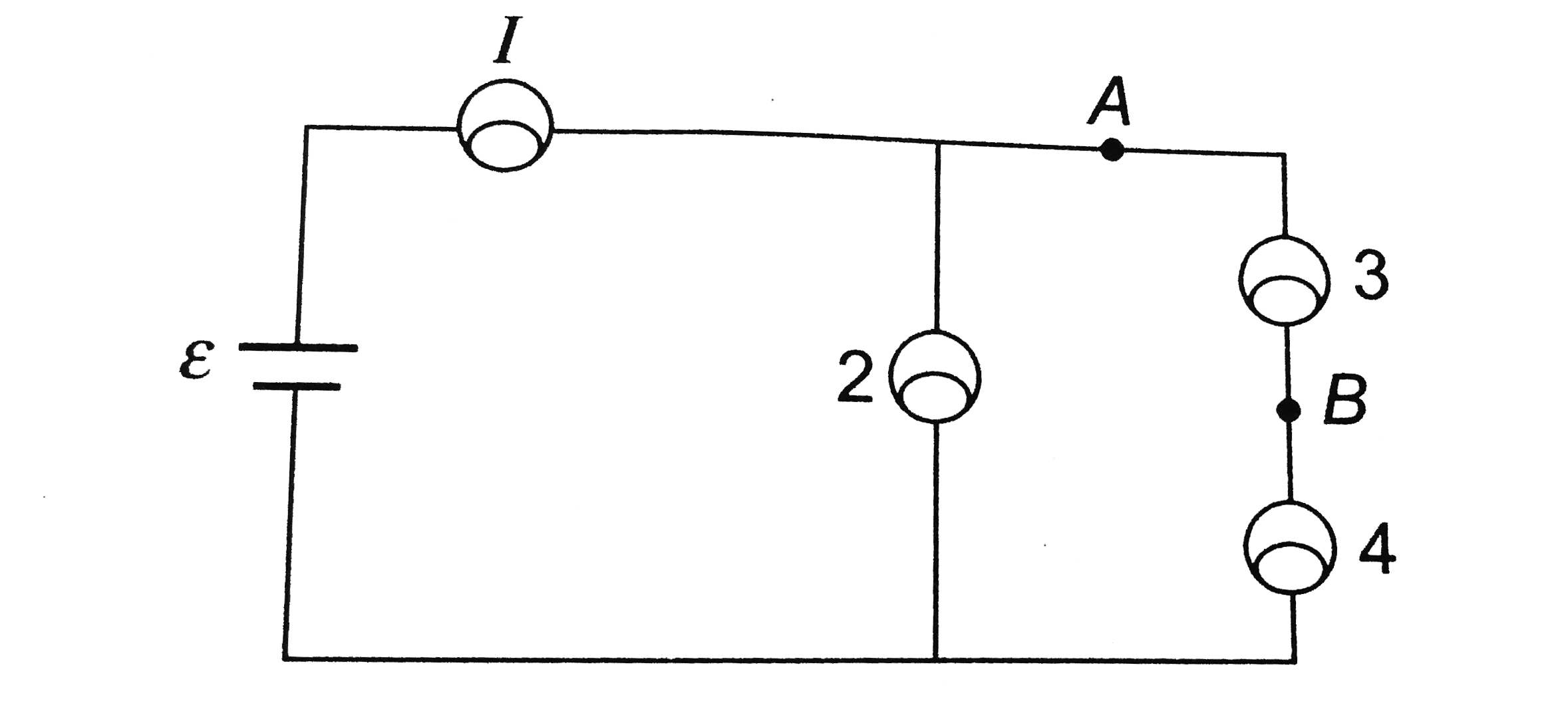
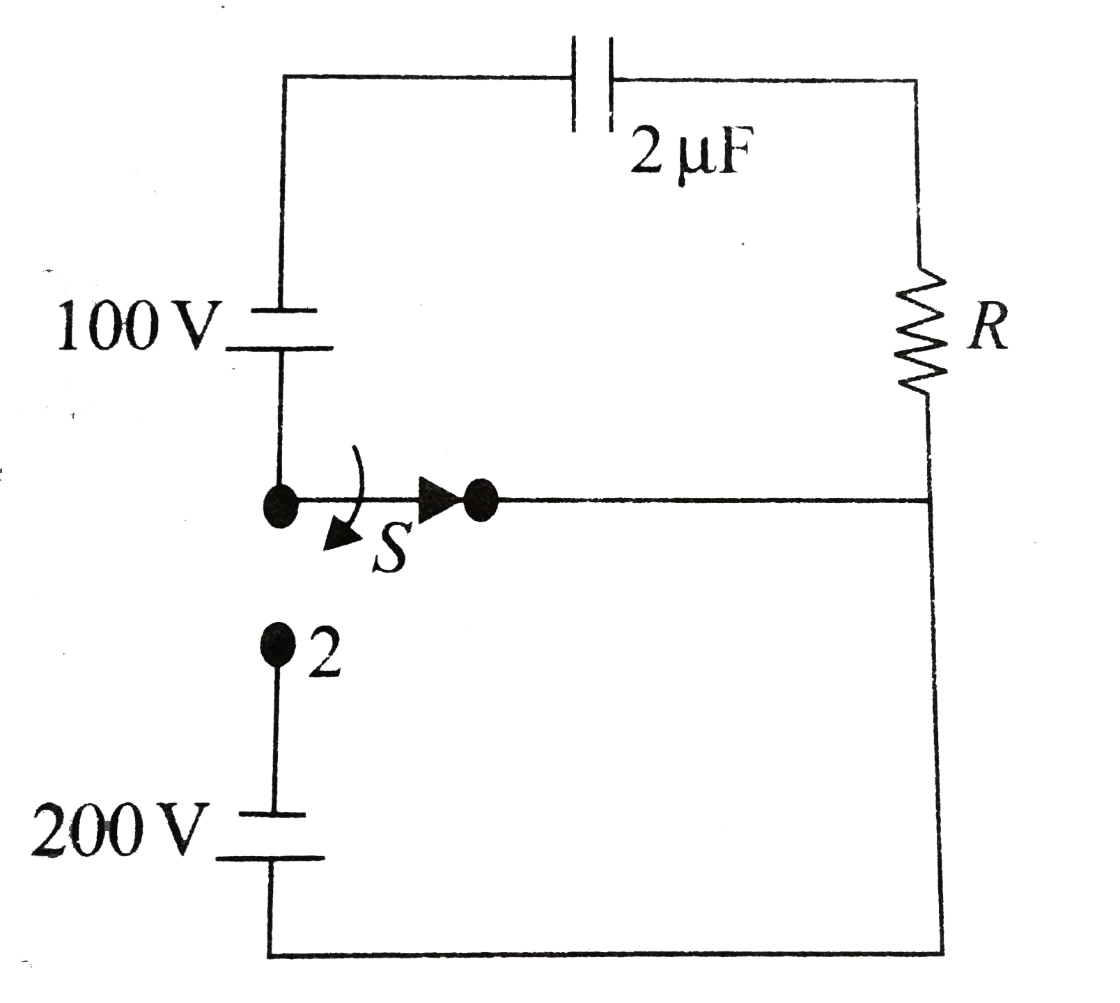
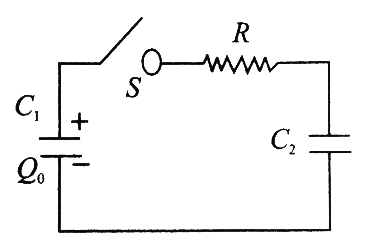
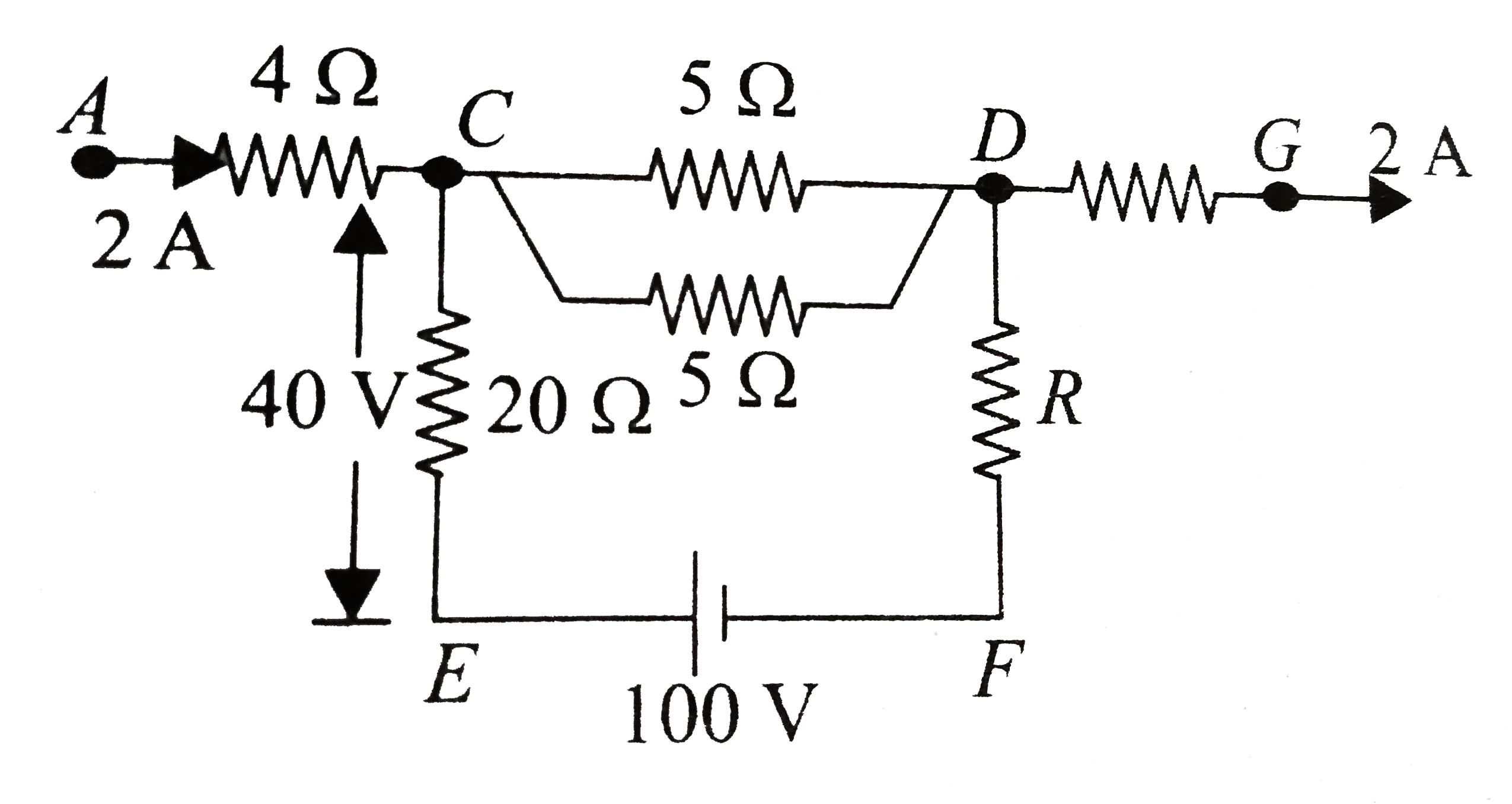
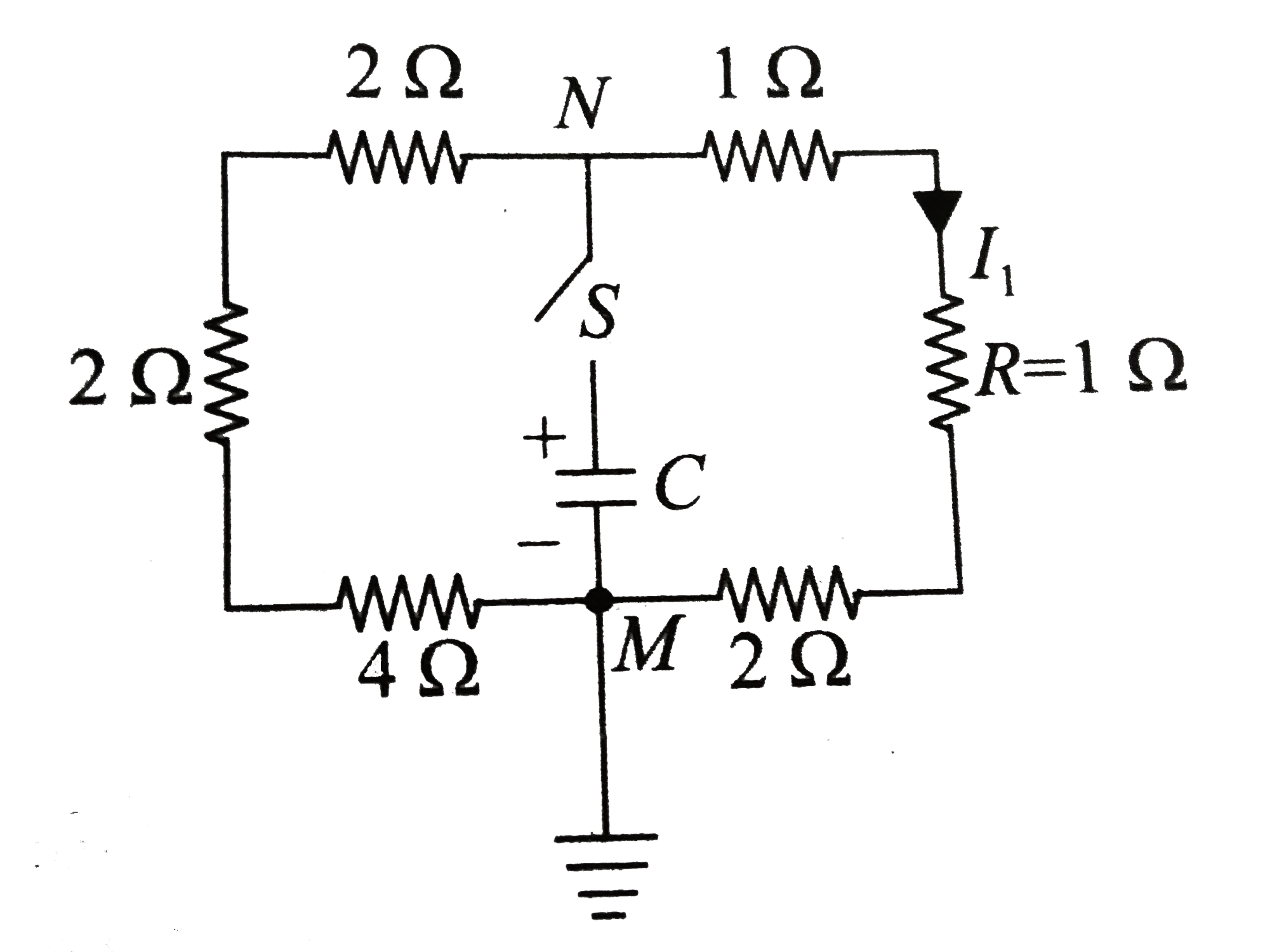
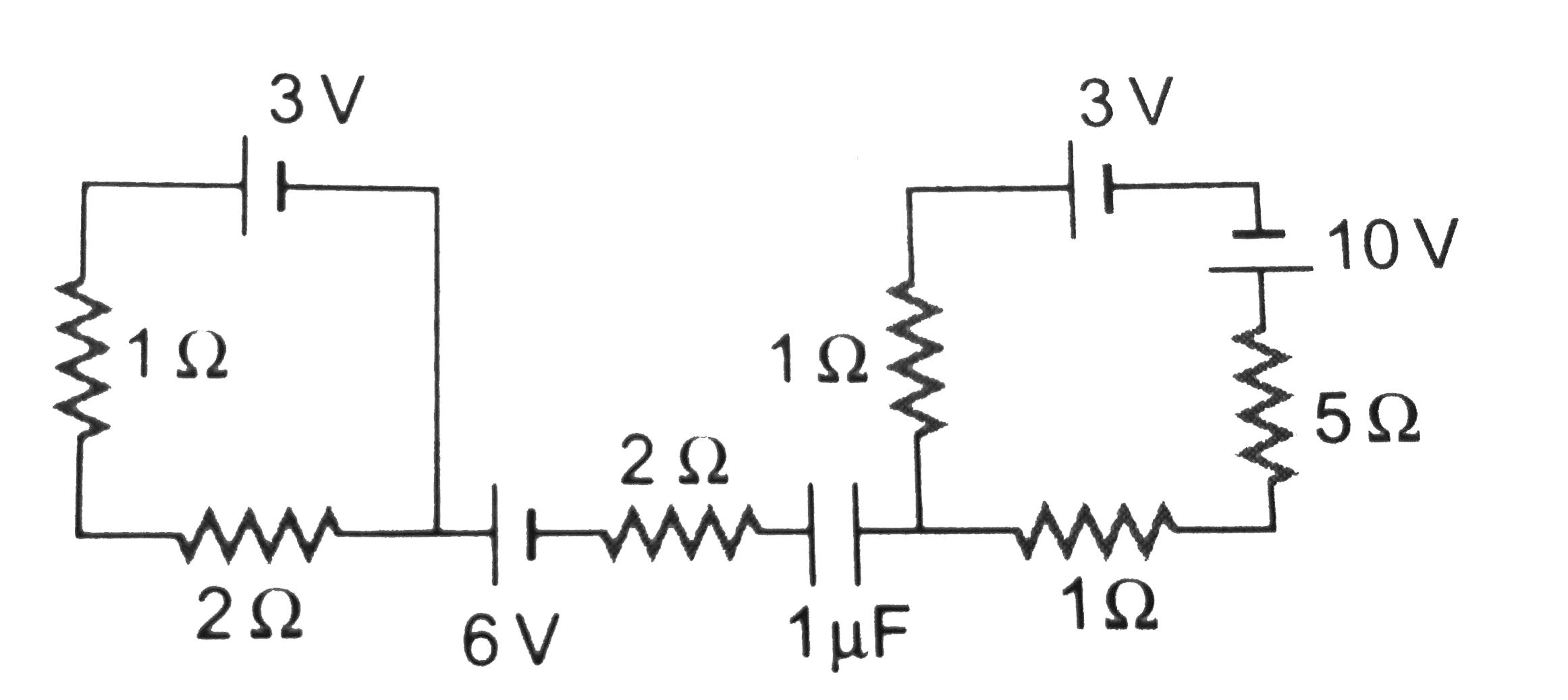
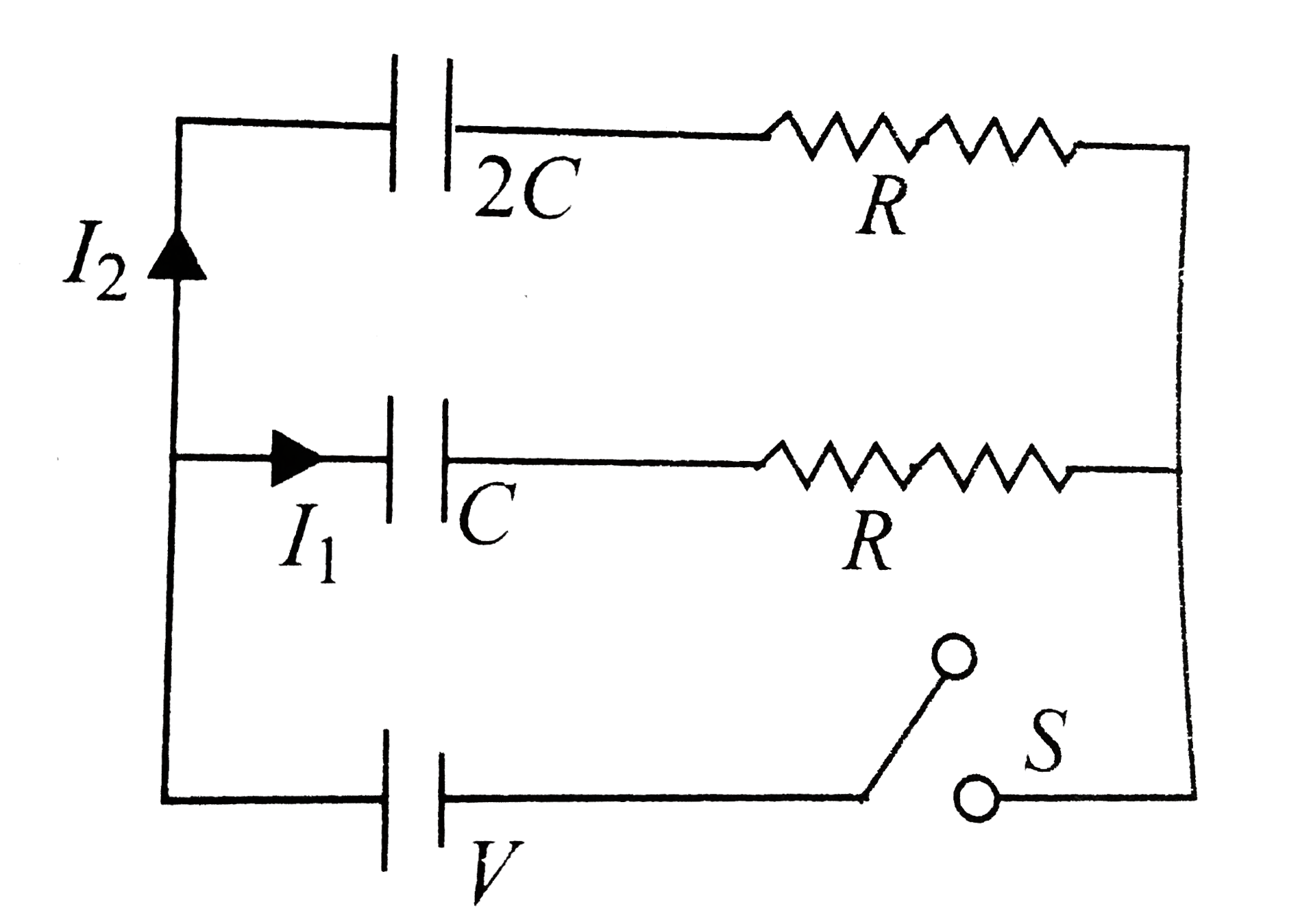
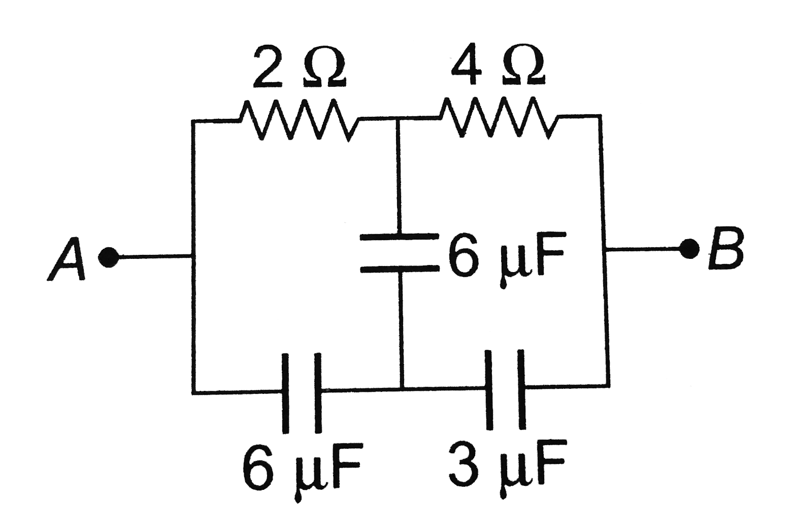
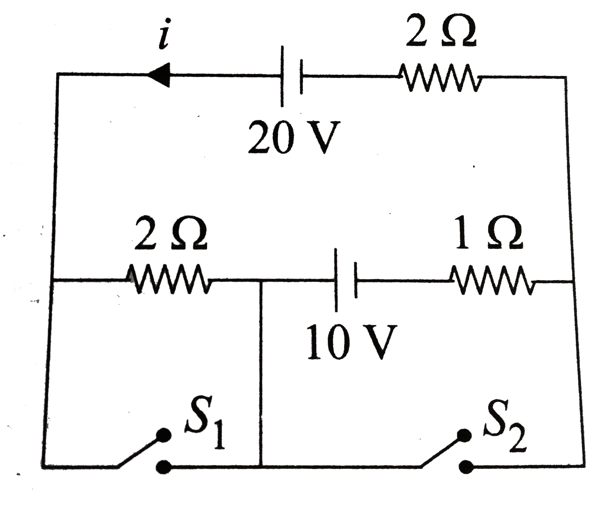
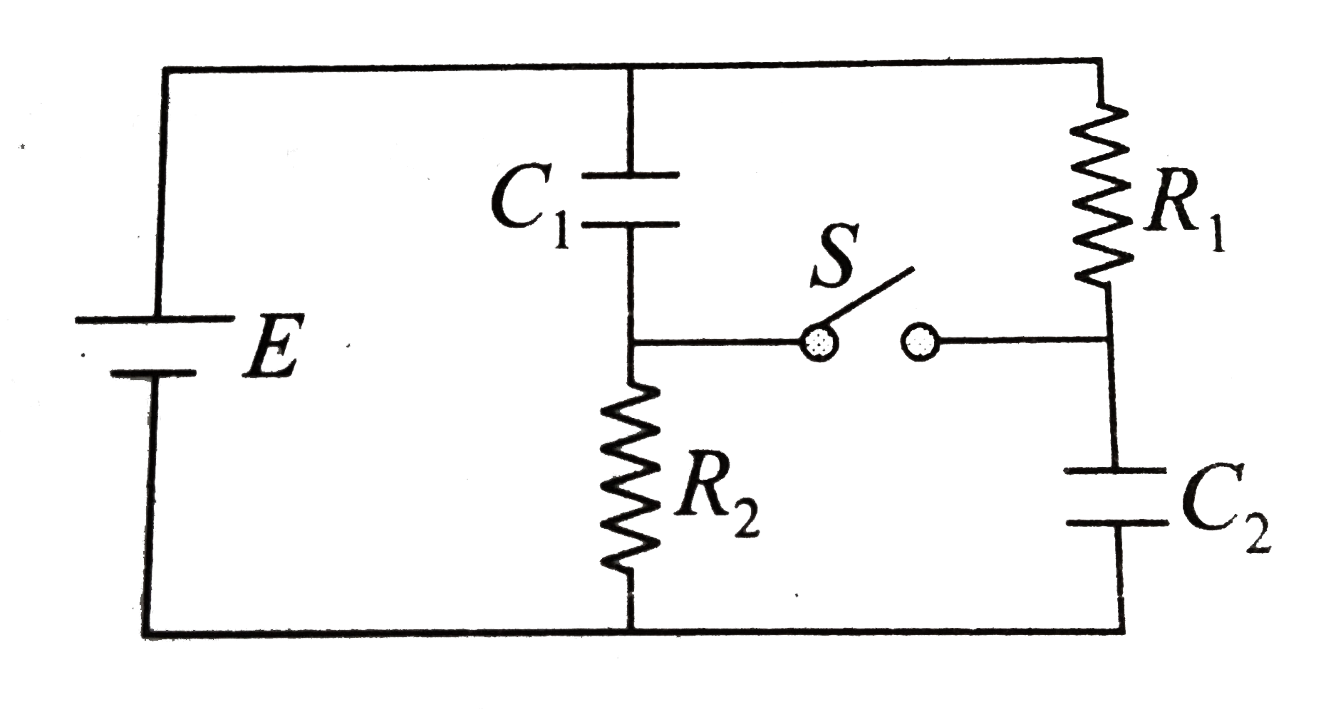
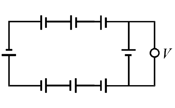
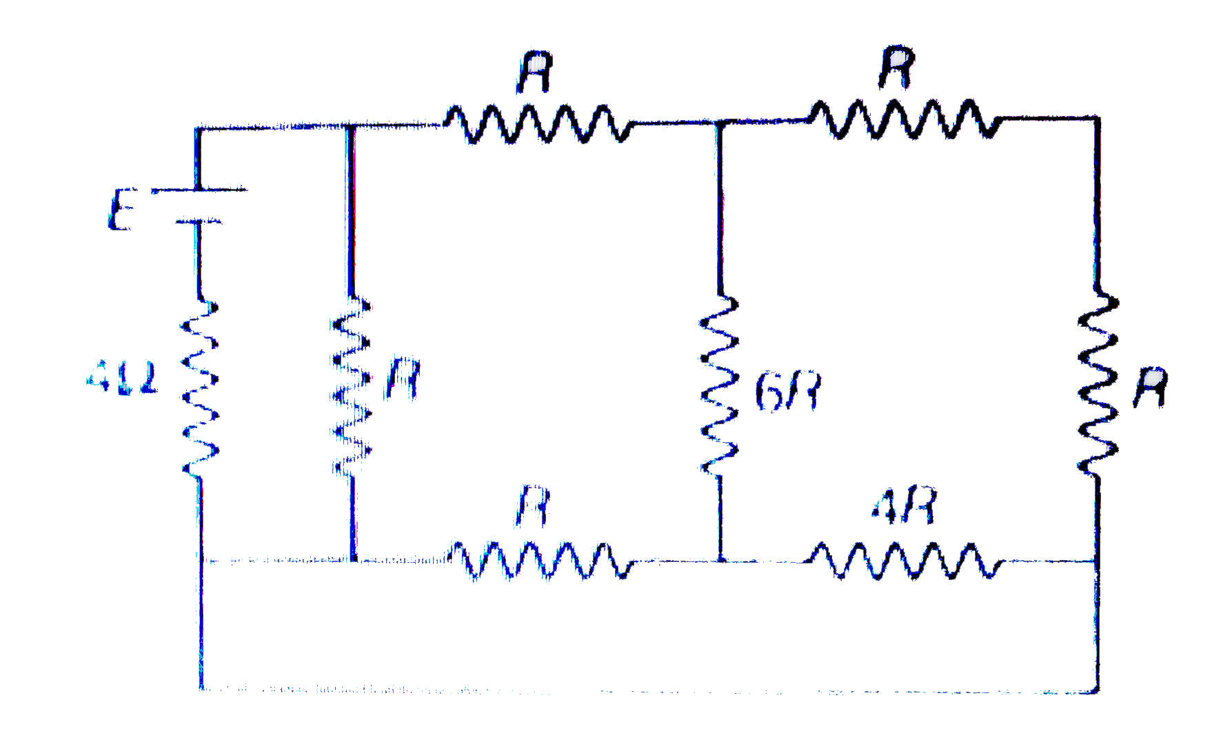
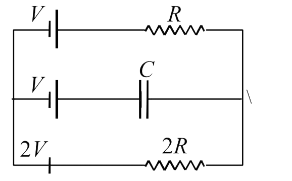
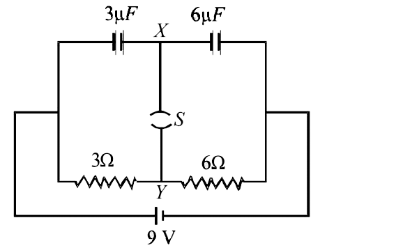
An 80μC charge is given to the 4μF capacitor in the circuit shown in Fig. so thae upper plate A is positively charged. An unknown resistance R is connected in the left limb. As soon as the switch S in the central limb is closed, a current of 2 A flows through the 2Ω resistor in the central limb. The capa citive time constant for the circuit is
 View Solution
Question 21
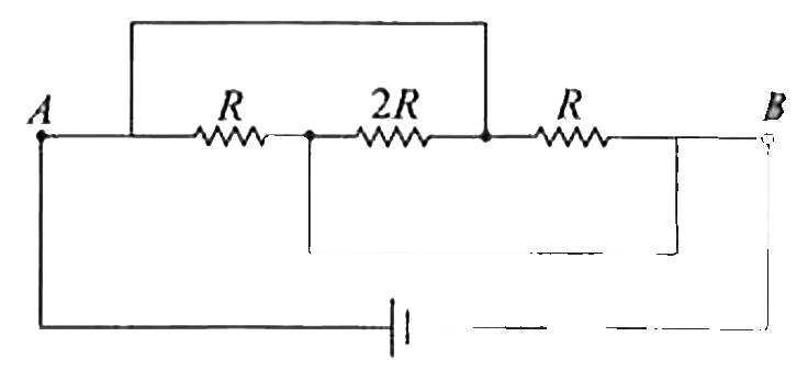
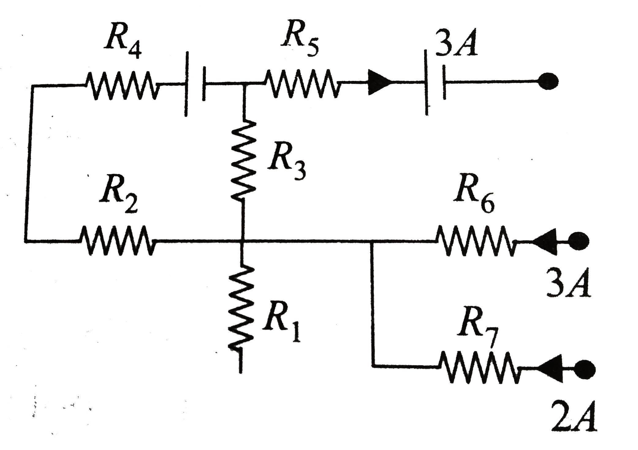
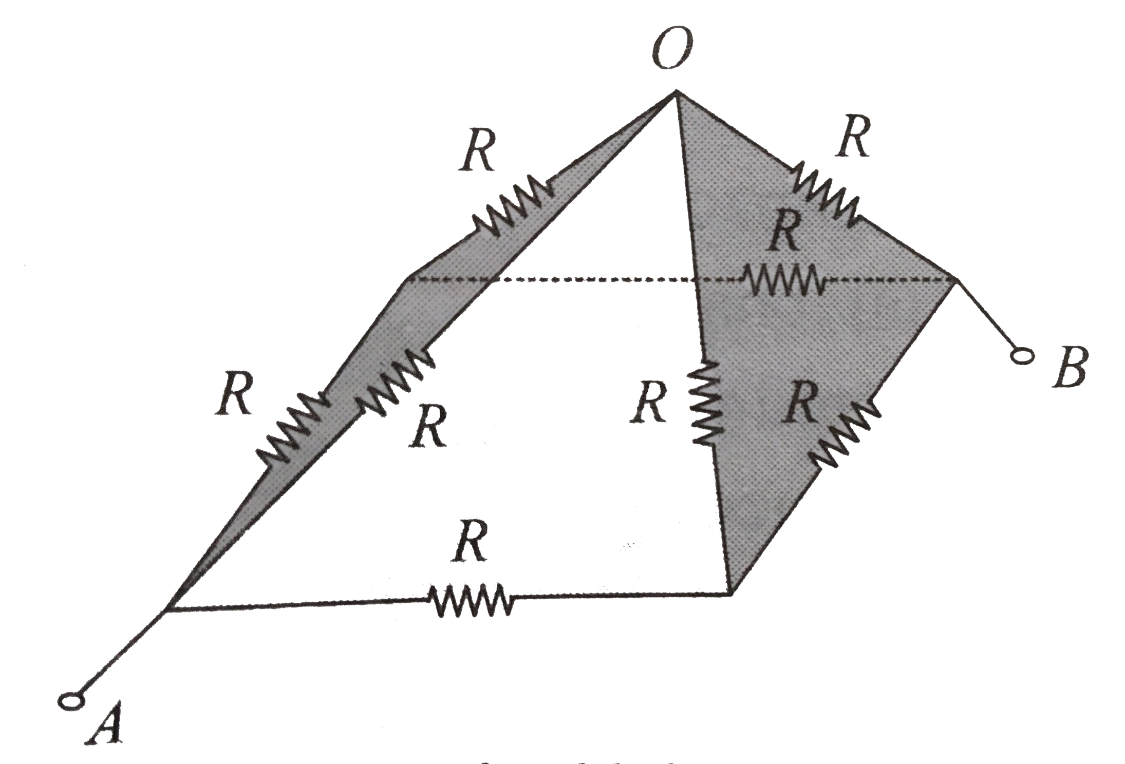
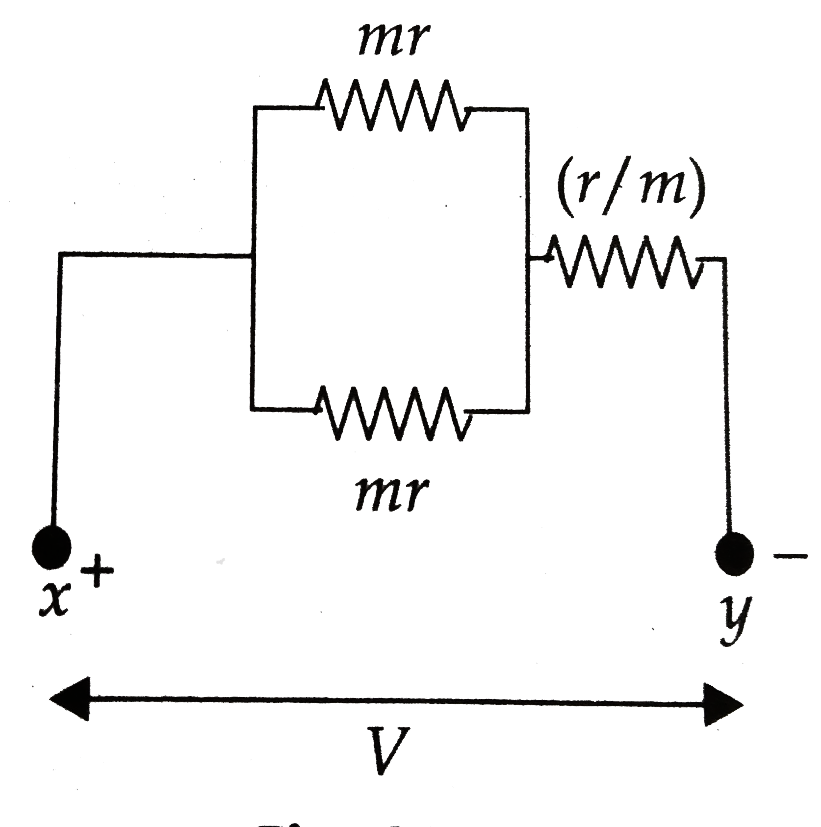
A piece of conducting wire of resistance R is cut into 2n equal parts. Half the parts are connected in series to form a bundle and remaining half in parallel to form another bundle. These bundles are then connected to give the maximum resistance. The maximum resistance of the combination is View SolutionQuestion 27
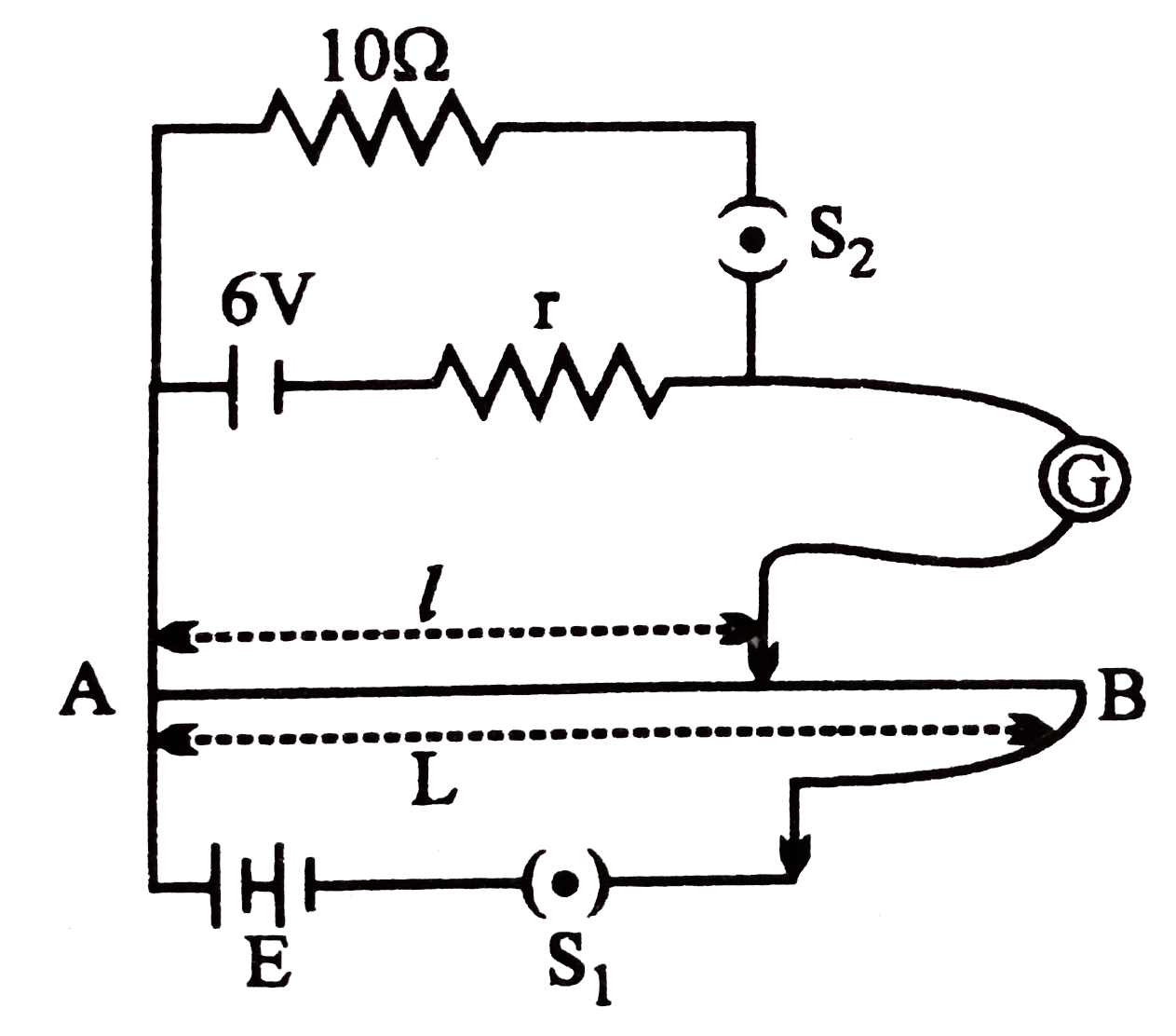
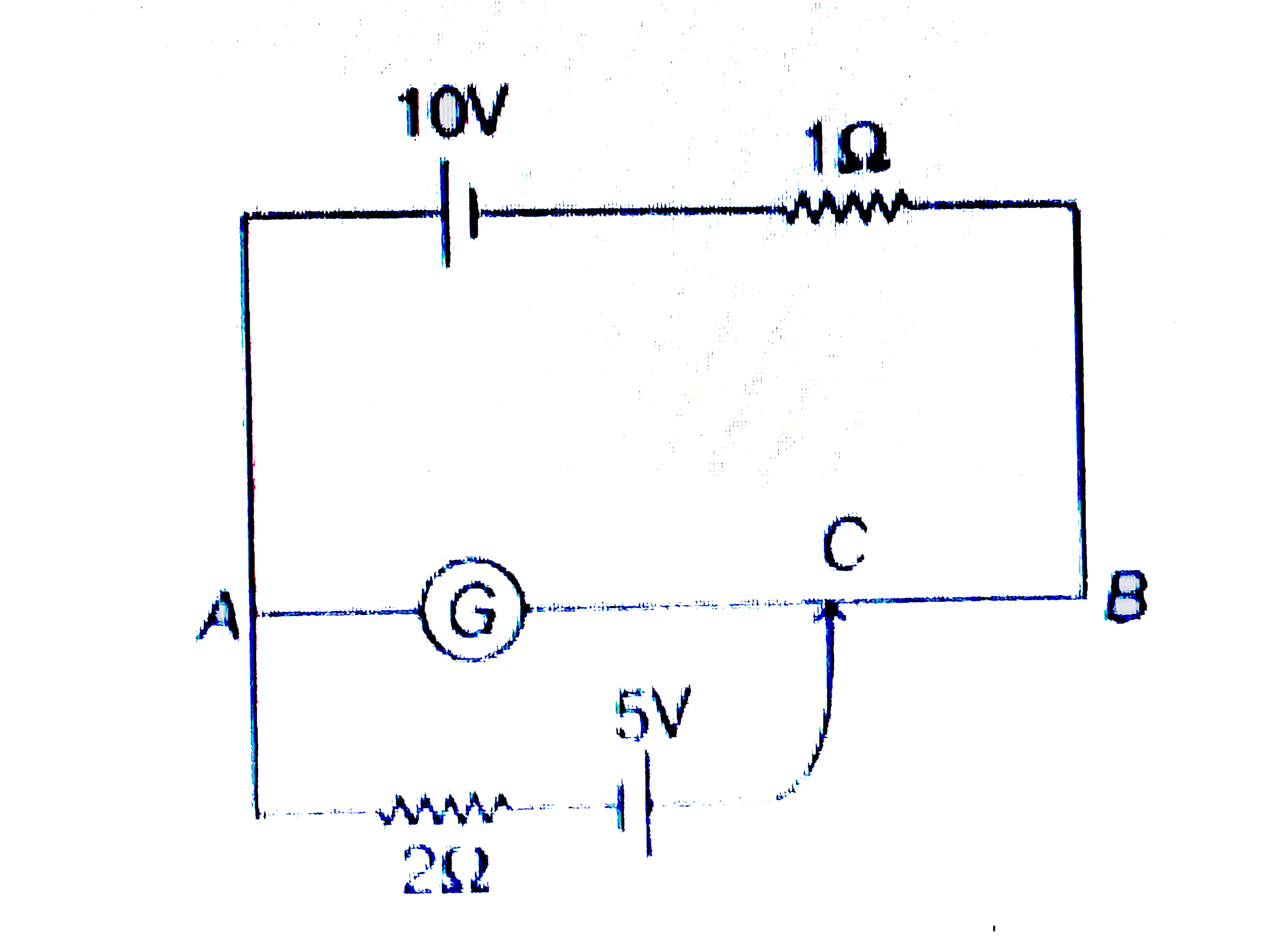
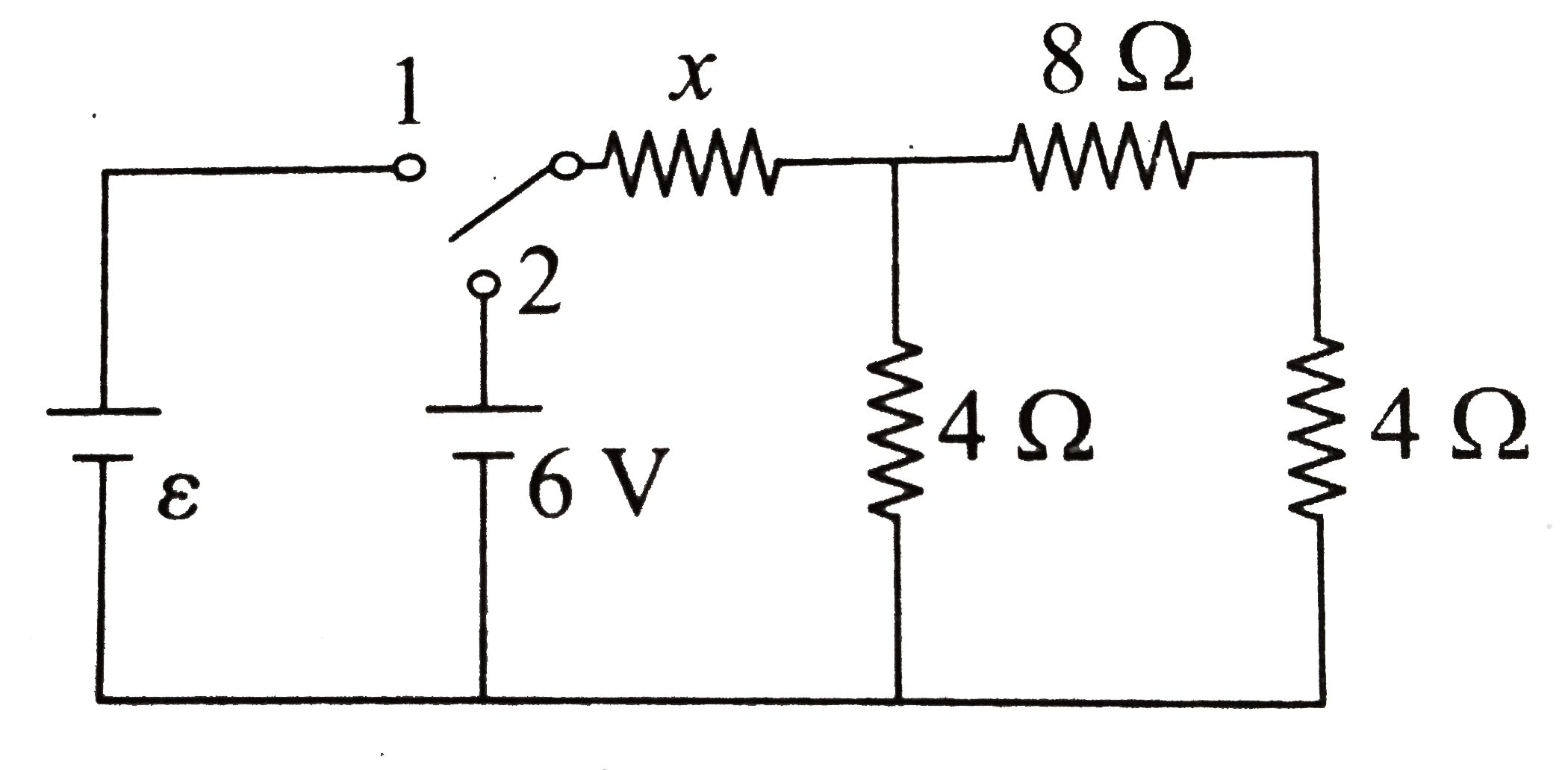
In the arrangement shown in figure when the switch S2 is open, the galvanometer shown no deflection for l=L/2. When the switch S2 is closed, the galvanometer shown no deflection for l=5L/12. The internal resistance (r) of 6V cell, and the emf E of the other battery are respectively
 View Solution
Question 38
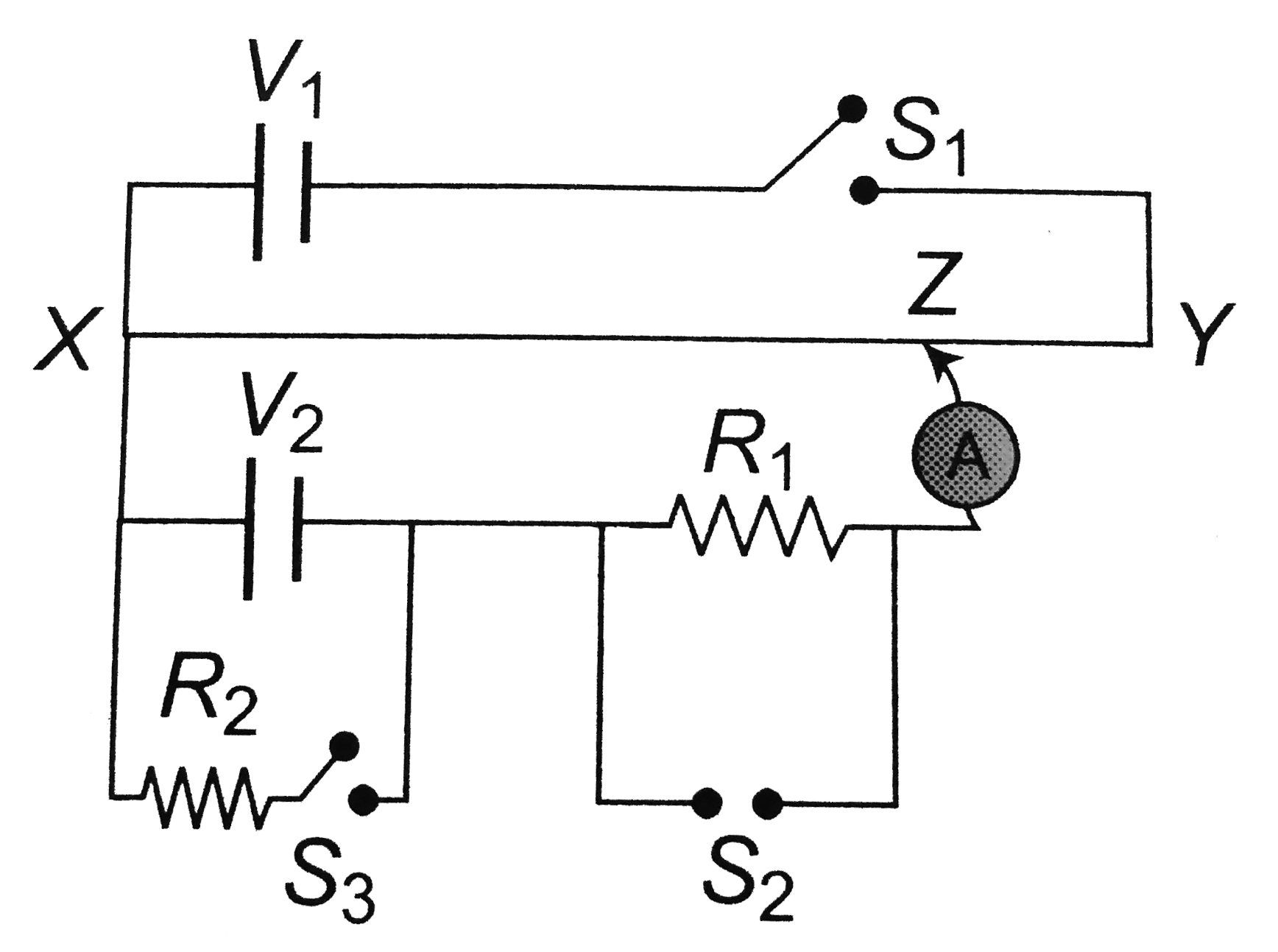
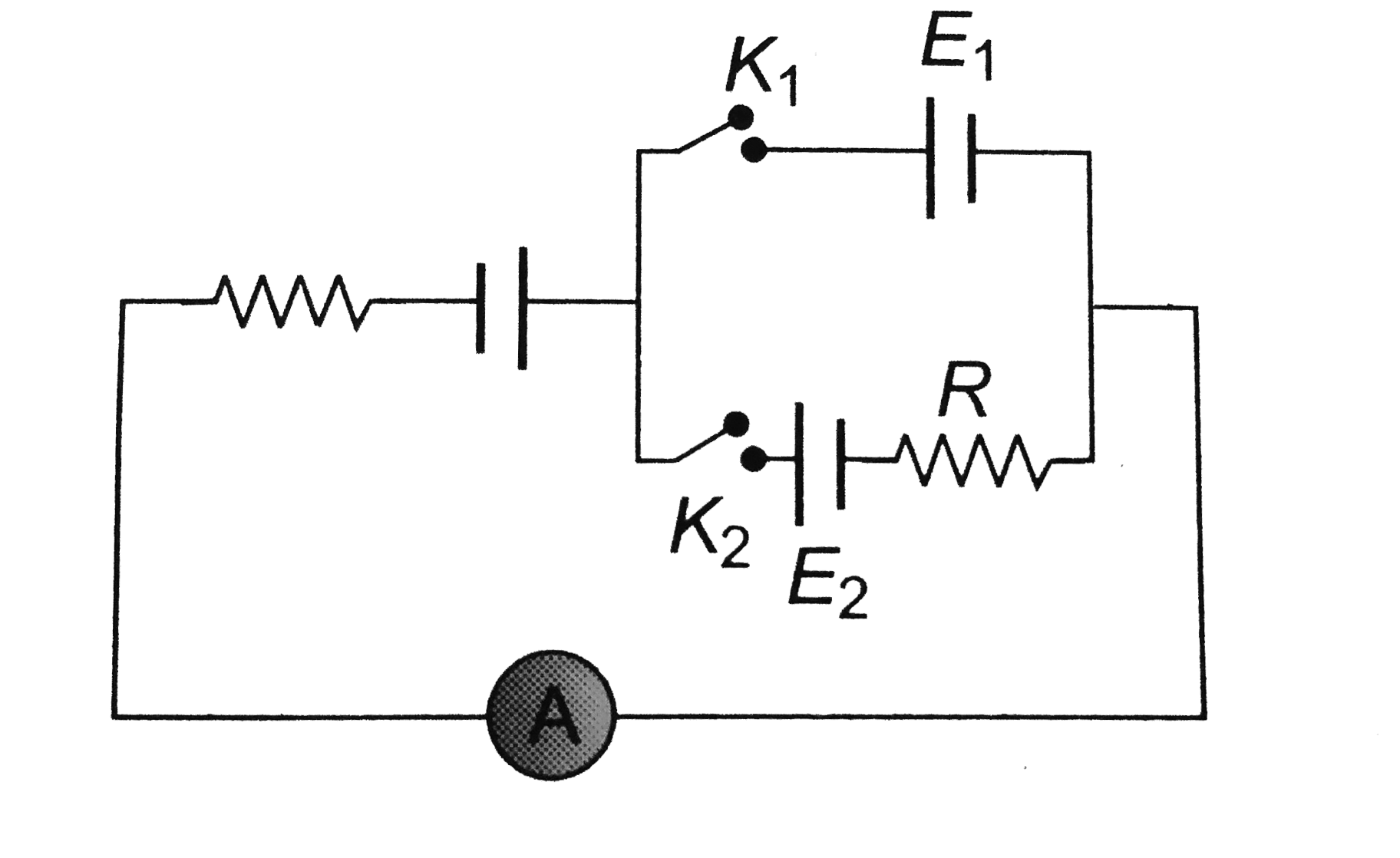
In the circuit shown if figure, XY is potentiometer wire 100cm long. The circuit is connected as shown. With switches S2 and S3 open, a balance point is found at Z. After switched S1 has remaind closed for some time, it is found that contact at Z must be moved towards Y to maintain a balance. which of the following in most likely reason for this ?
 View Solution
Question 41
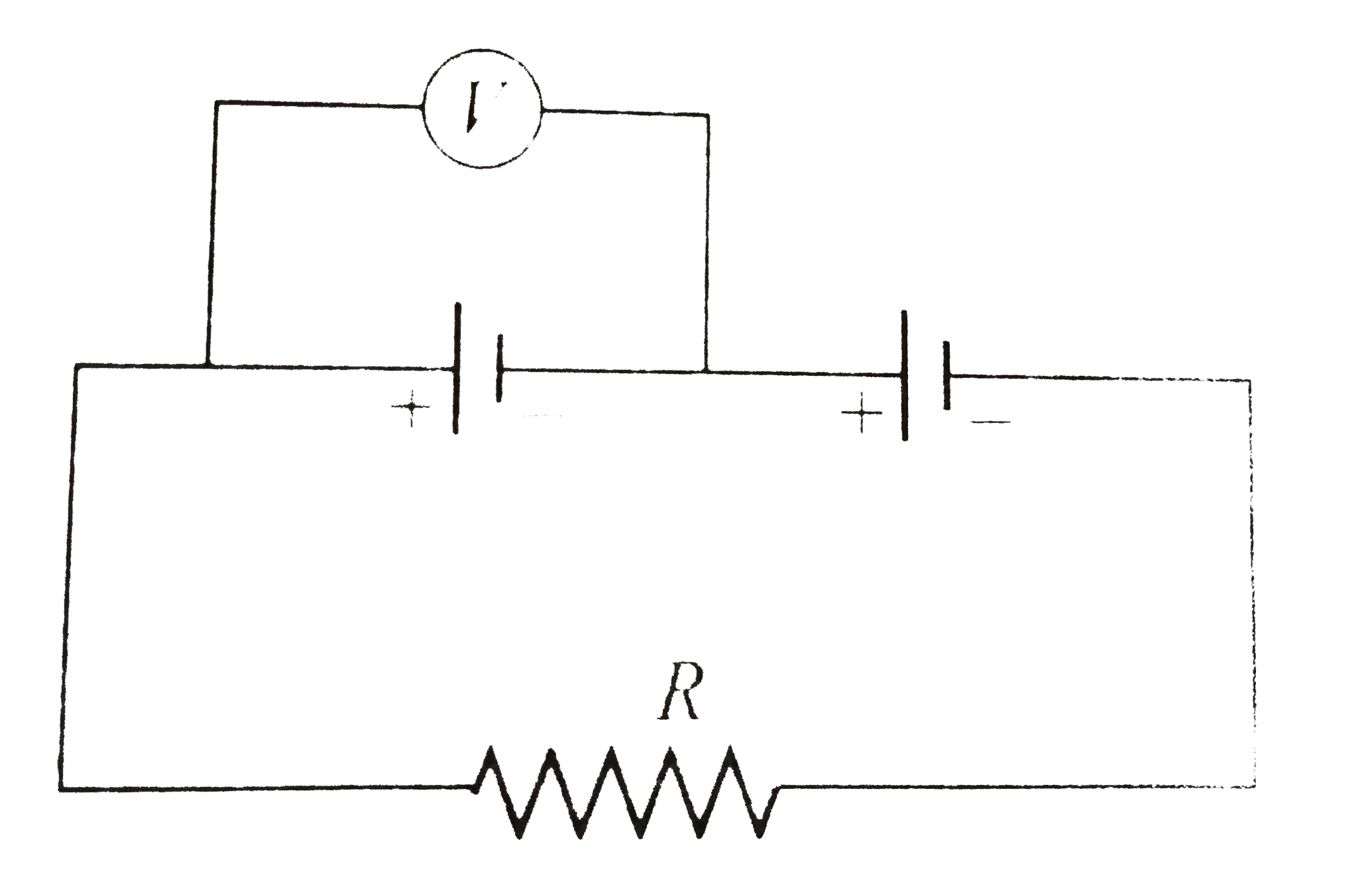
shows a circuit used in an experiment to detrmine the emf and interanl resistance of the battery C. A graph was plotted of the potential difference V between the terminals of the battery against the current I, which was varied by adjusting the rheostat. The graph is shown in x and y are the intercepts of the graph with the axes as shown. What is the internal resistance of the battery?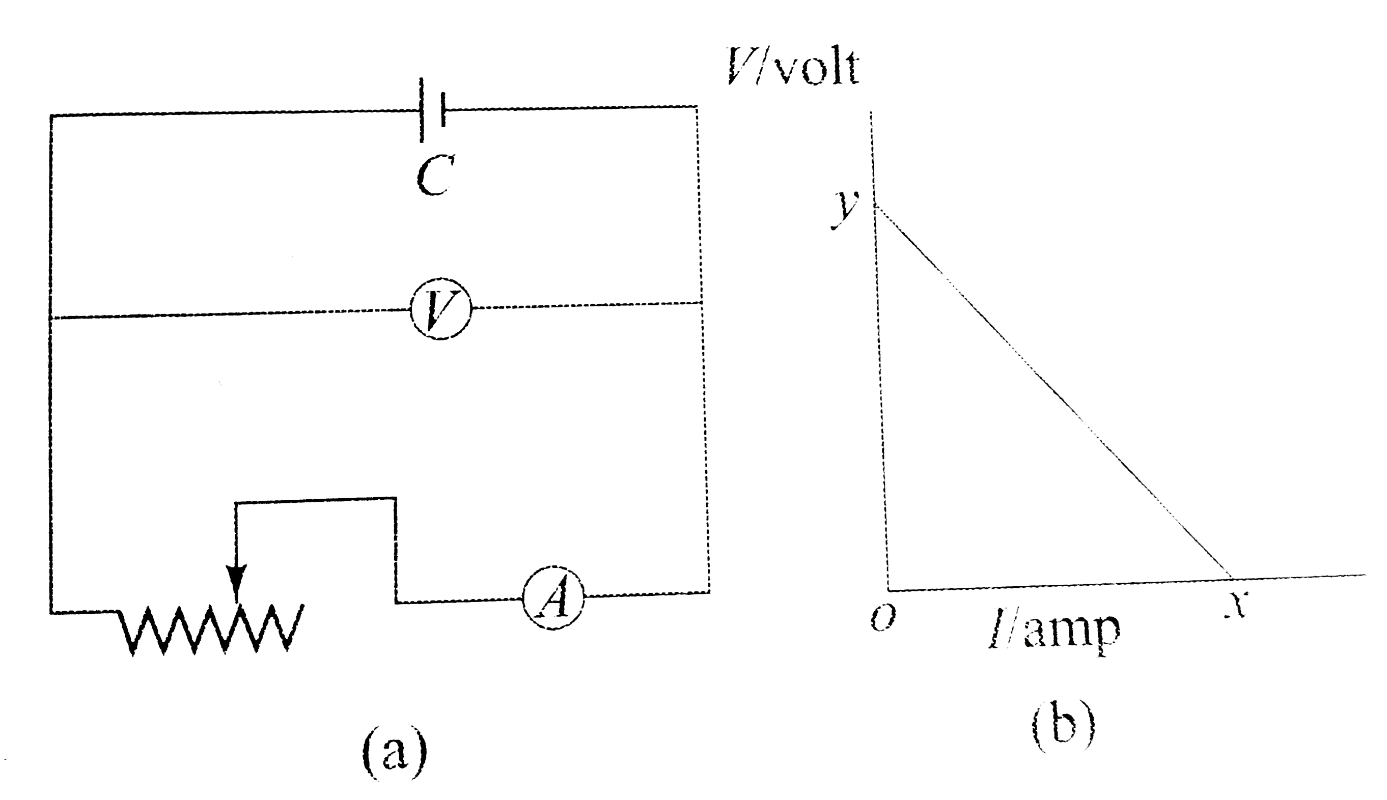 View Solution
Question 48
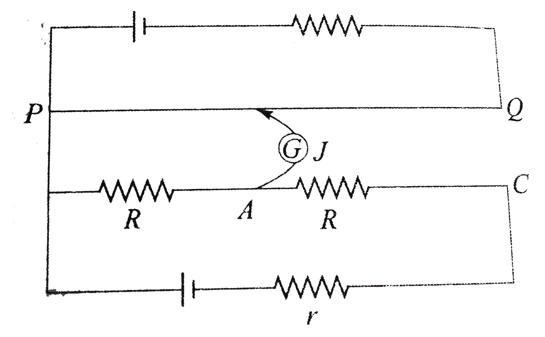
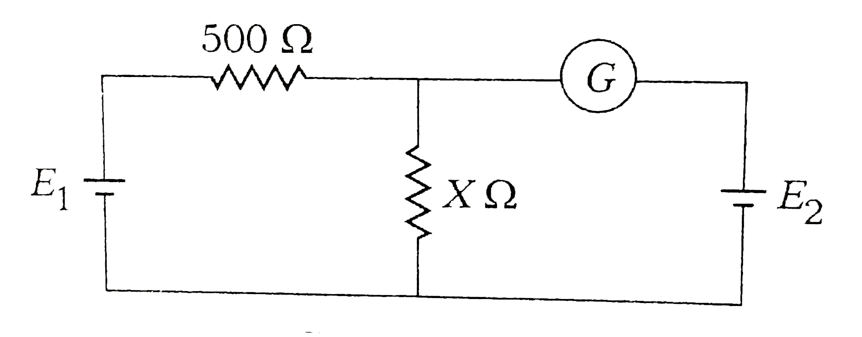
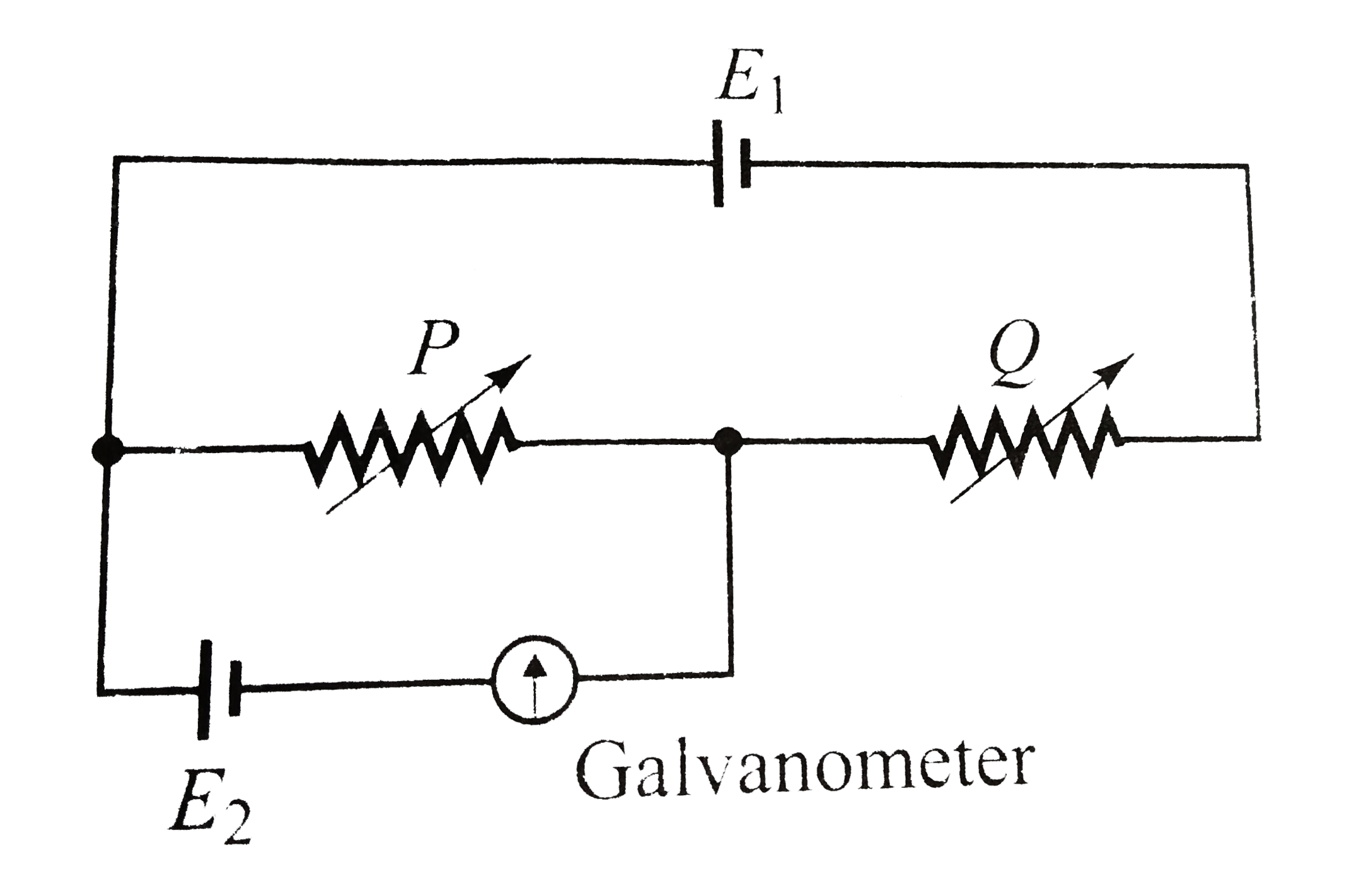
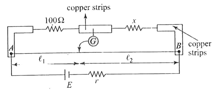
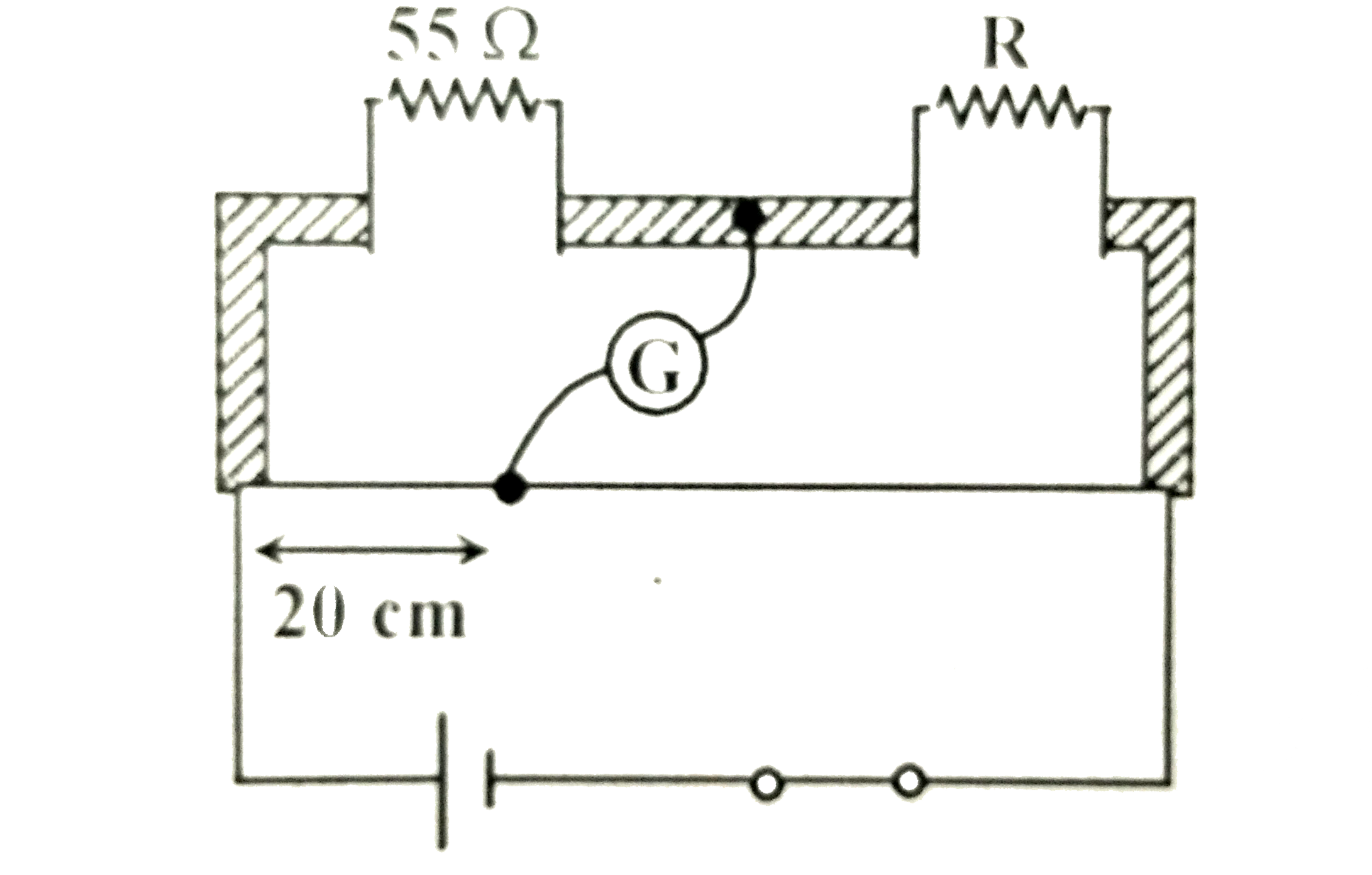
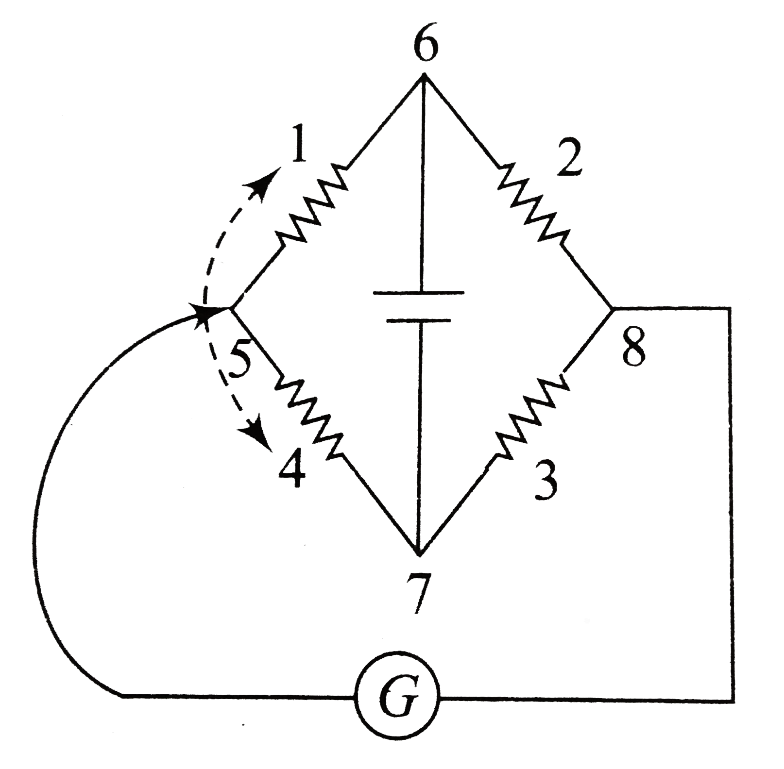
Circuit for the measurement of resistance by potentiometer is shown in figure. The galvanometer is first connected at point A and zero deflection is observed at length PJ=10cm. In second case, it is connected at point C and zero deflection is observed at a length 30 cm from P, then the unknown resistance X is .
 View Solution
Question 52
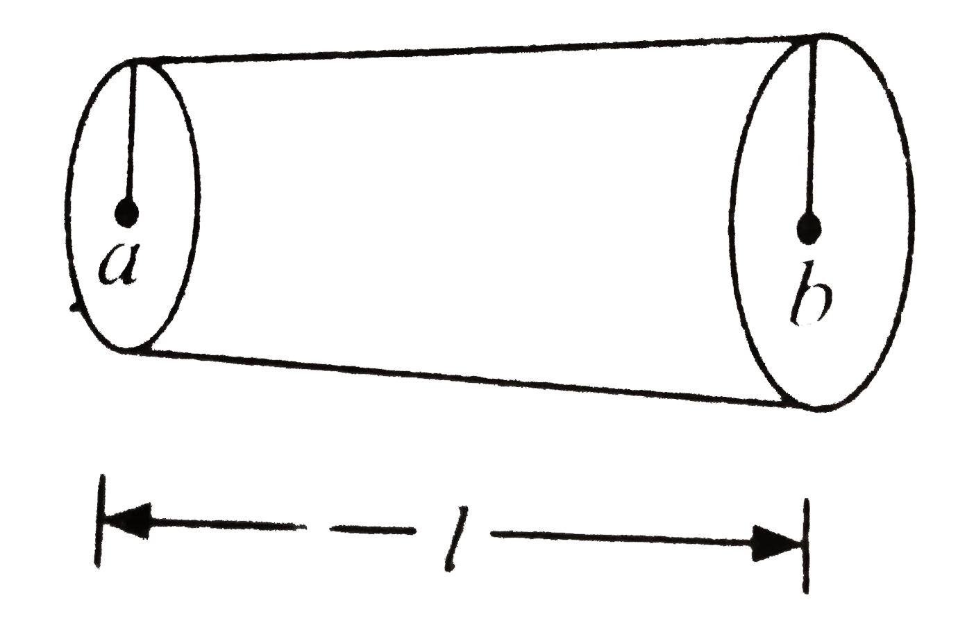
Two long coaxial and conducting cylinders of radius a and b are separated by a material of conductivity σ and a constant potential difference V is maintained between them by a battery. Then the current per unit length of the cylinder flowing from one cylinder to the other is View SolutionQuestion 66
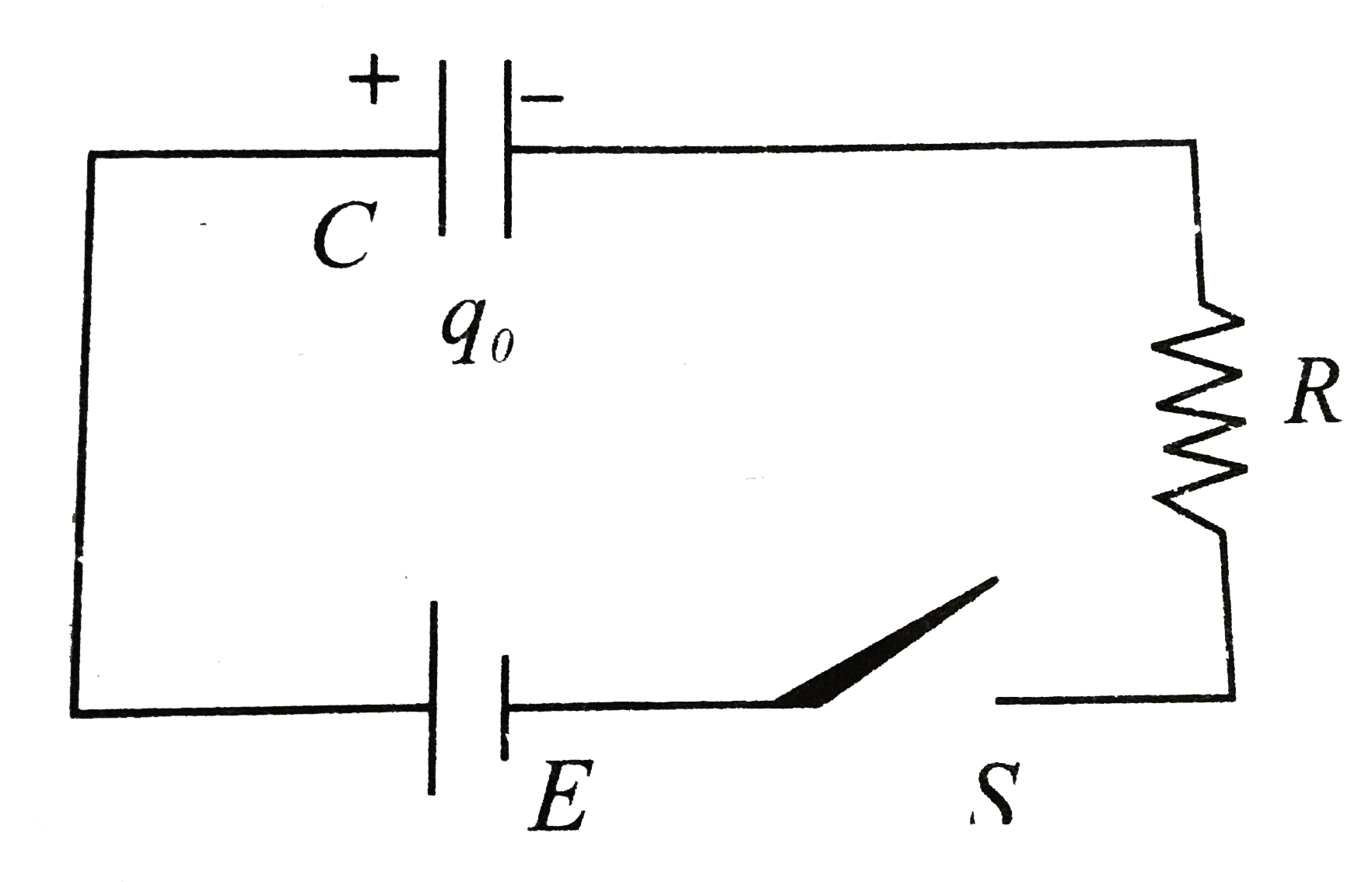
A capacitor of capacitance 10mF is charged up a potential difference of 2V and then the cell is removed. Now it is connected to a cell of emf4V and is charged fully. In both cases the polarities of the two cells are in the same directions. Total heat produced in the second charging process is :View SolutionQuestion 69
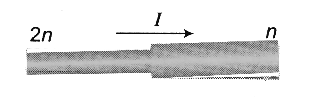
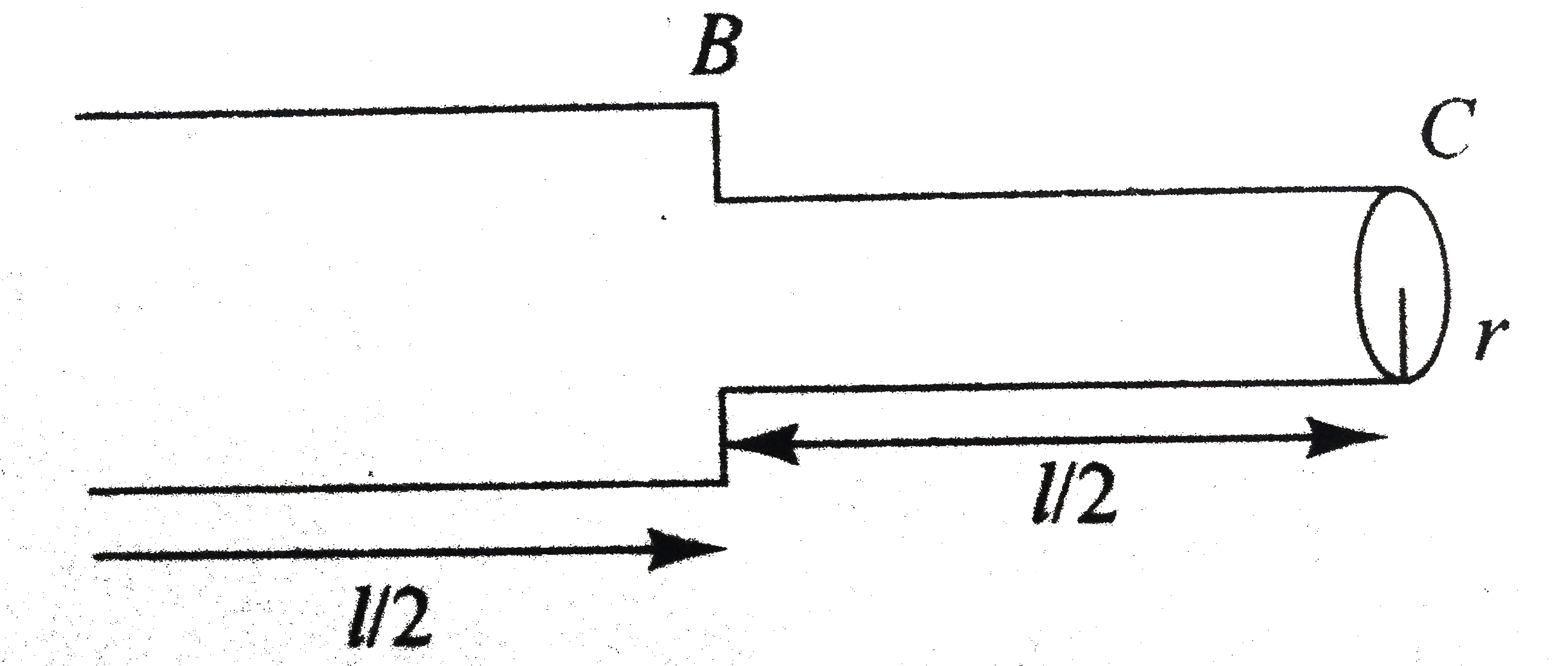
Two cylindrical rods of uniform cross-section area A and 2A, having free electrons per unit volume 2n and n respectively are joined in series. A current I flows through them in steady state. Then the ratio of drift velocity of free electron in left rod to drift velocity of electron in the
right rod is (vLvR) is
 View Solution
Question 72

A potentiometer wire AB as shown in 40 cm long of resistance 50Ω/m free end of an ideal galvanometer is touching the potentiometer wire with the help of a jockey. What should be the velocity of the jockey as a function of time so that potential difference across the galvanometer is varying with time as (2sinπt)VView SolutionQuestion 77
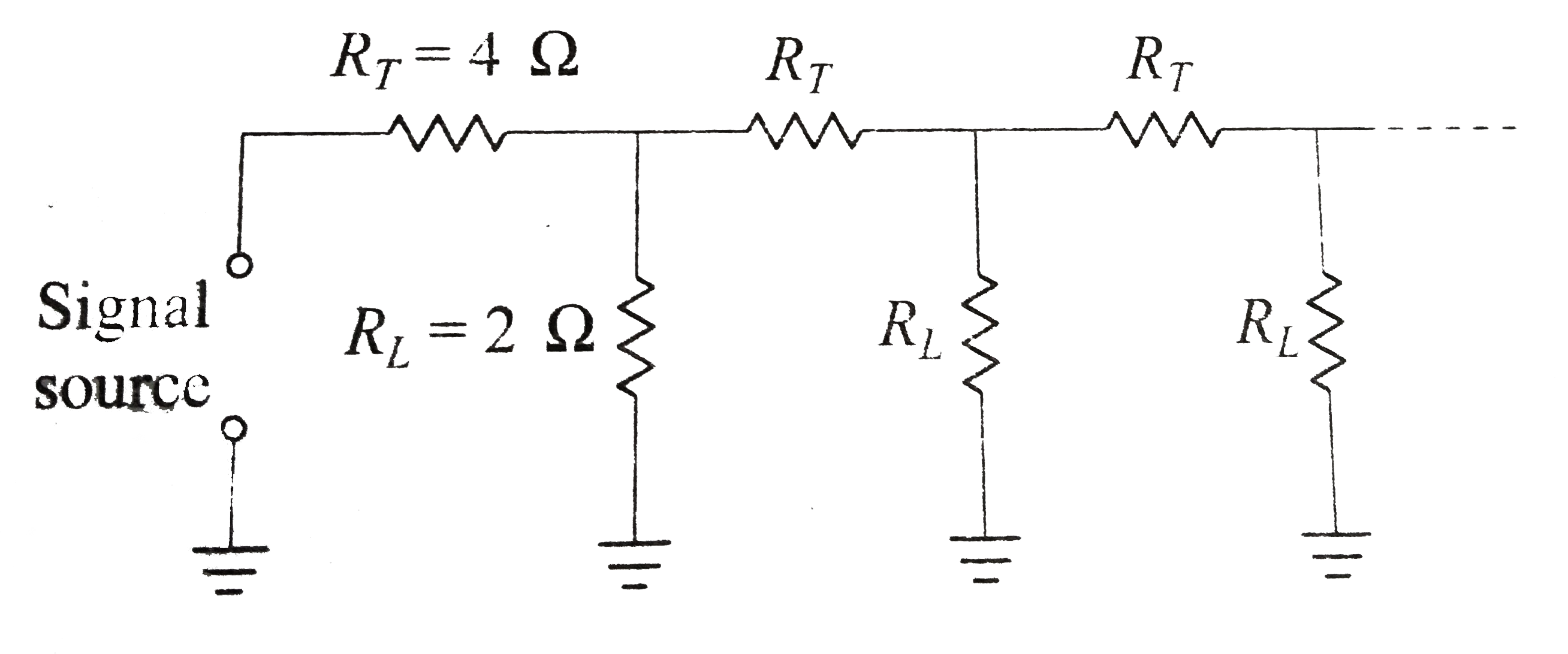
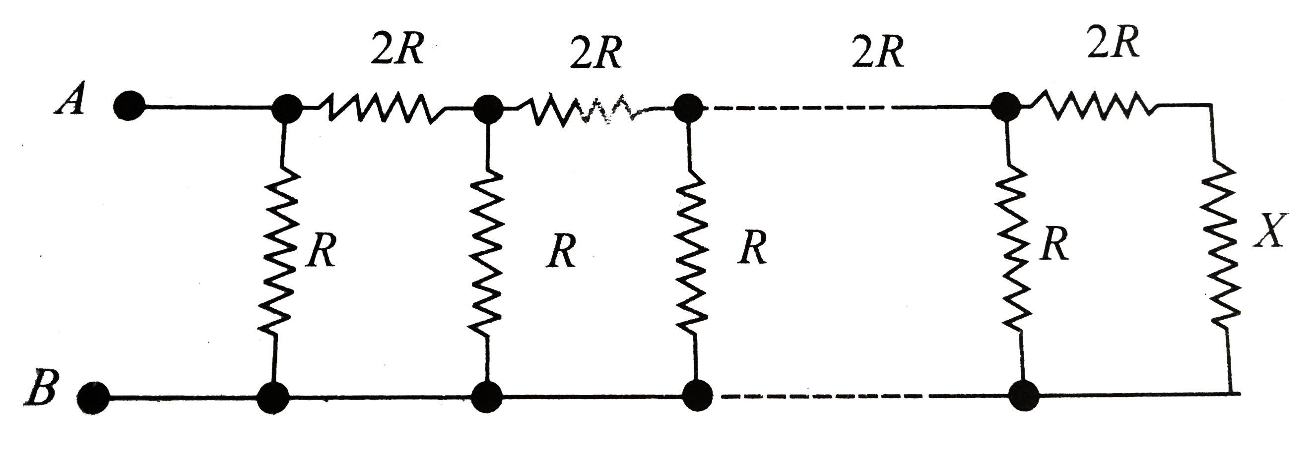
Figure shows a circuit model for the transmission of an electrical signal, such as cable TV, to a large number of subscribers. Each subscriber connects a load resistance RL between the transmission line and the ground. Assume the ground to be at zero potential and to have negligible resistance. The resistance of the transmission line between the connection points of different subscribers is modeled as the constant resistance RT. The equivalent resistance across the signal source is
 View Solution
Question 80
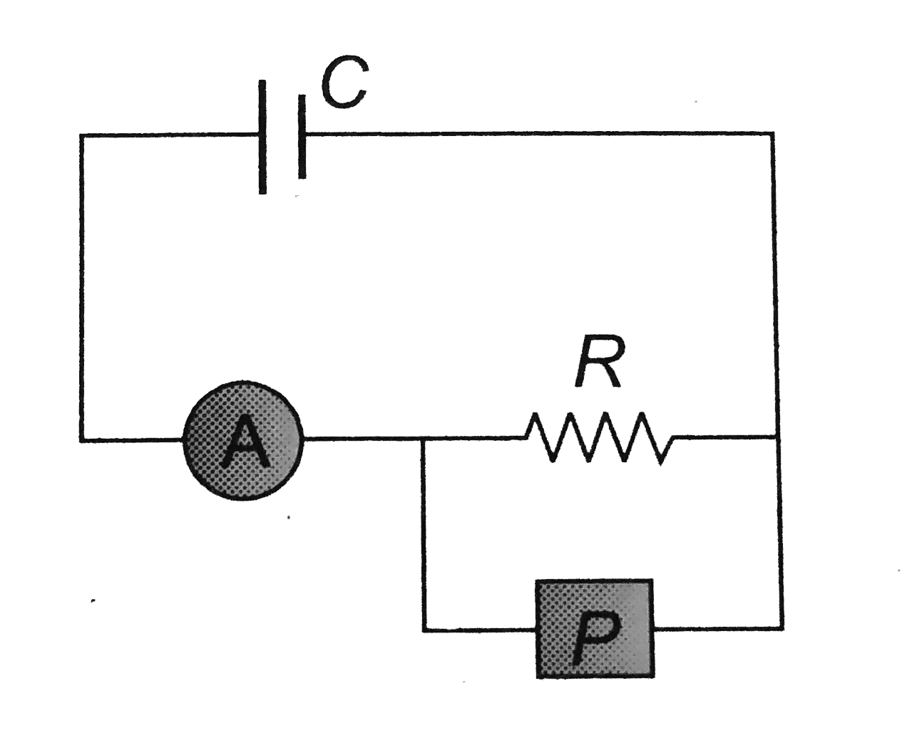
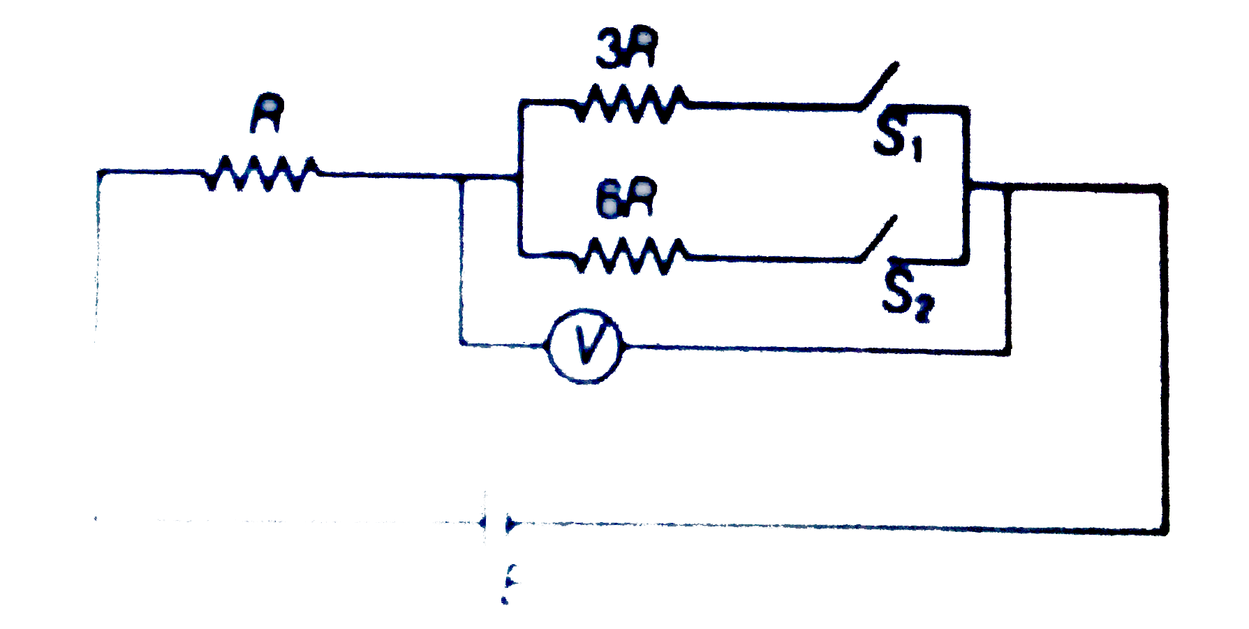
An ammeter A of finite resistance, and a resistor R are joined in series to an ideal cell C. A potentiometer P is joined in parallel to R. The ammeter reading is I0 and the potentiometer reading is V0. P is now replaced by a voltmeter of finite resistance. The ammeter reading now is I and the voltmeter reading is V.
 View Solution
Question 82
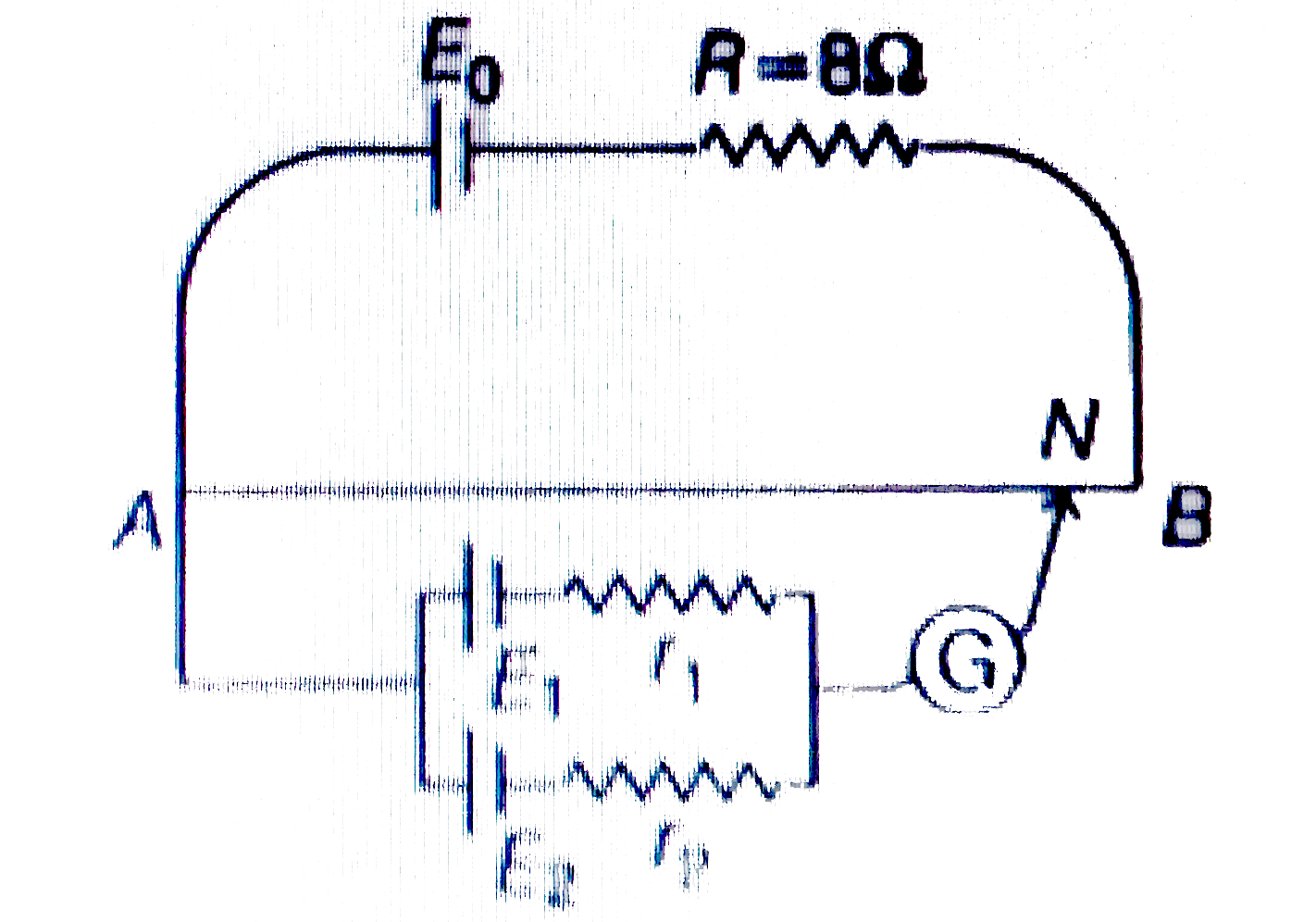
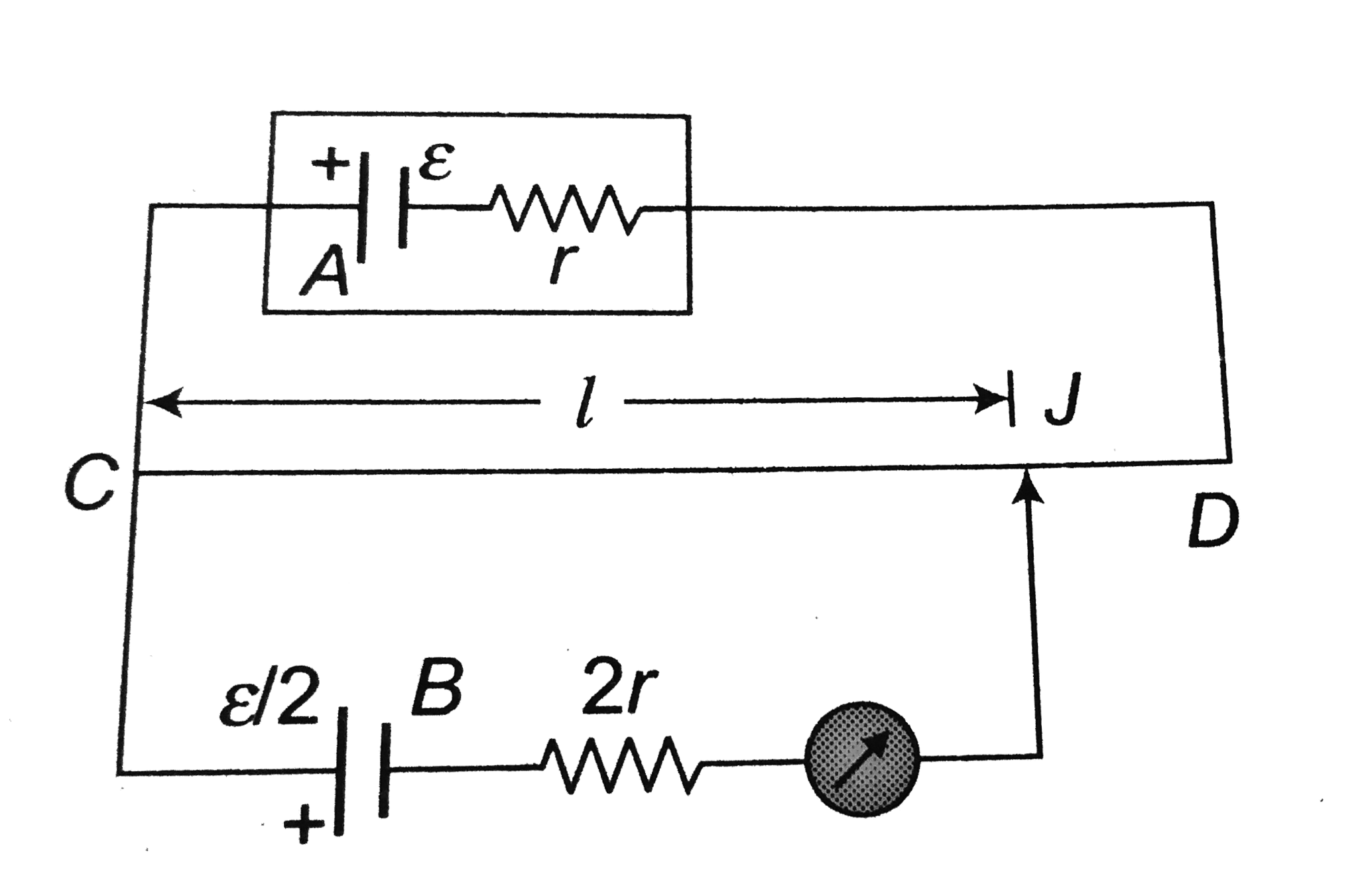
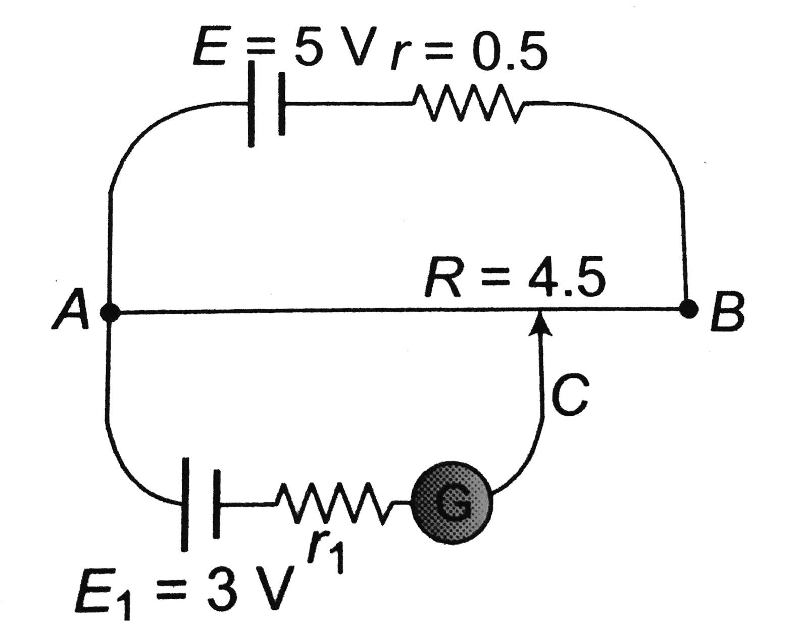
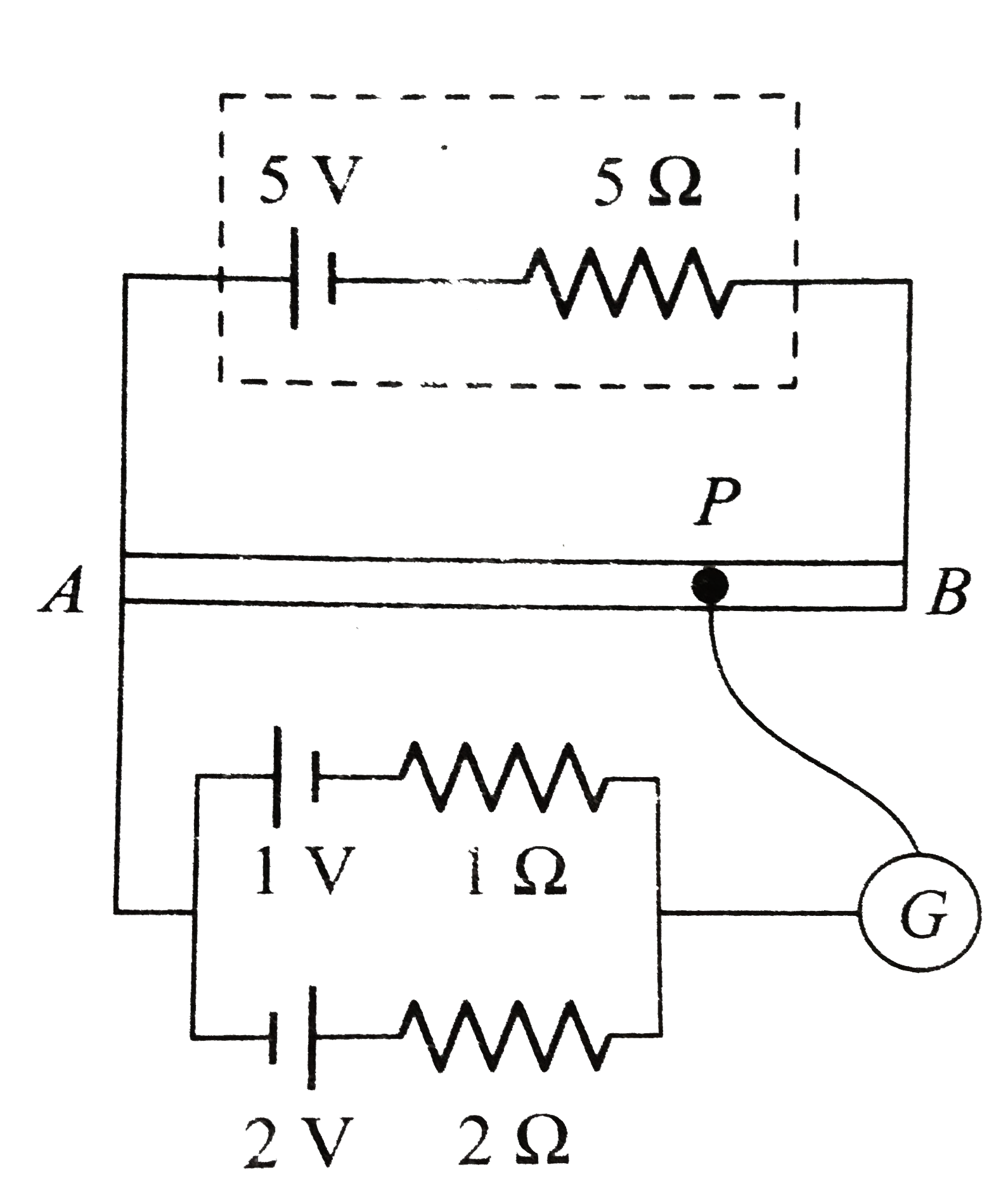
A battery of emf E0=12V is connected across a long uniform wire having resistance 4Ω−m. The cell of small emfs E1=2V and E2=4V having interest resistance 2Ω and 6Ω respecitvely, are connected shown in the figure. If galvanometer shows deflection at the point N, the distance of point from the point A is equal to
 View Solution
Question 88
A wire of length L and three identical cell of negligible internal resistance are connected in series. Due to the current, the temperature of wire is raised by ΔT in a time t. A number N of similar cells is now connected in series with a wire of the same material and cross section but of length 2L. The temperature of wire is raised by the same amount ΔT in the same time t. The value of N is View SolutionQuestion 89
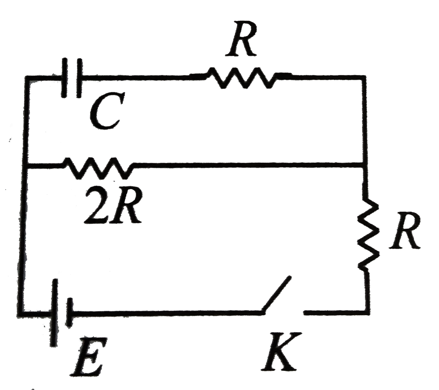
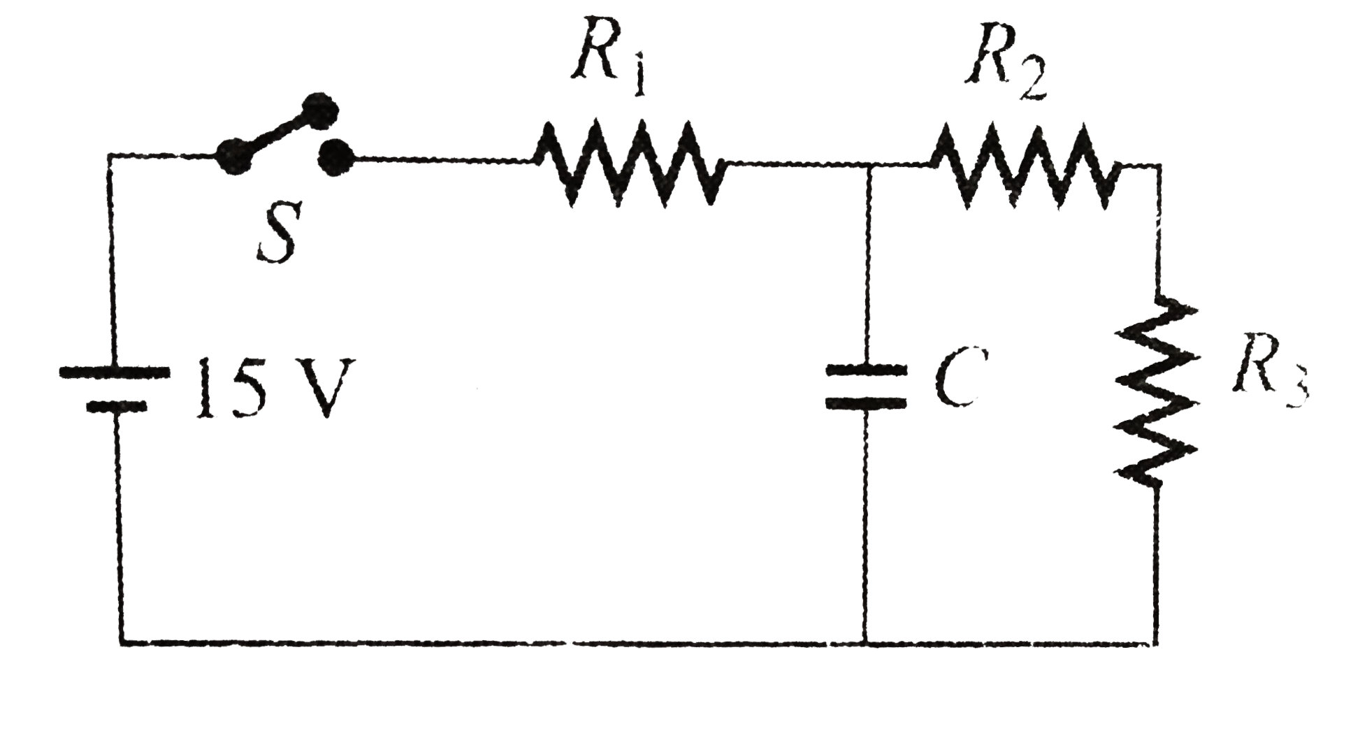
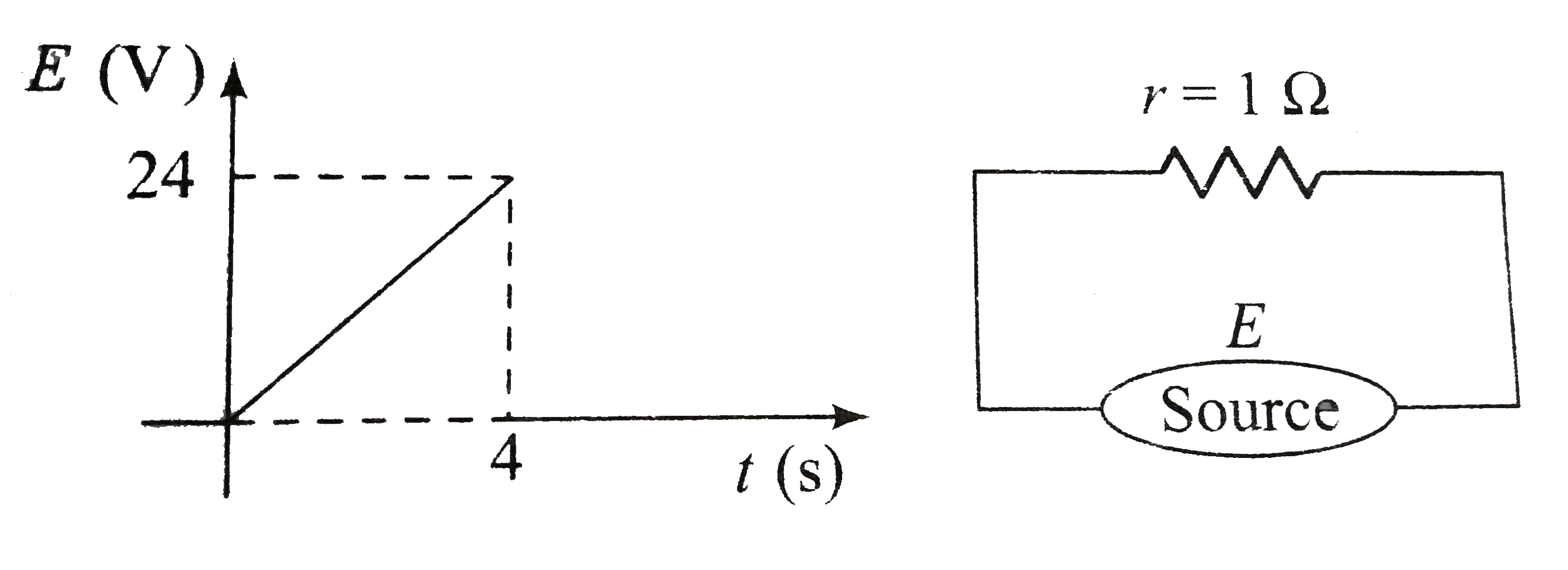
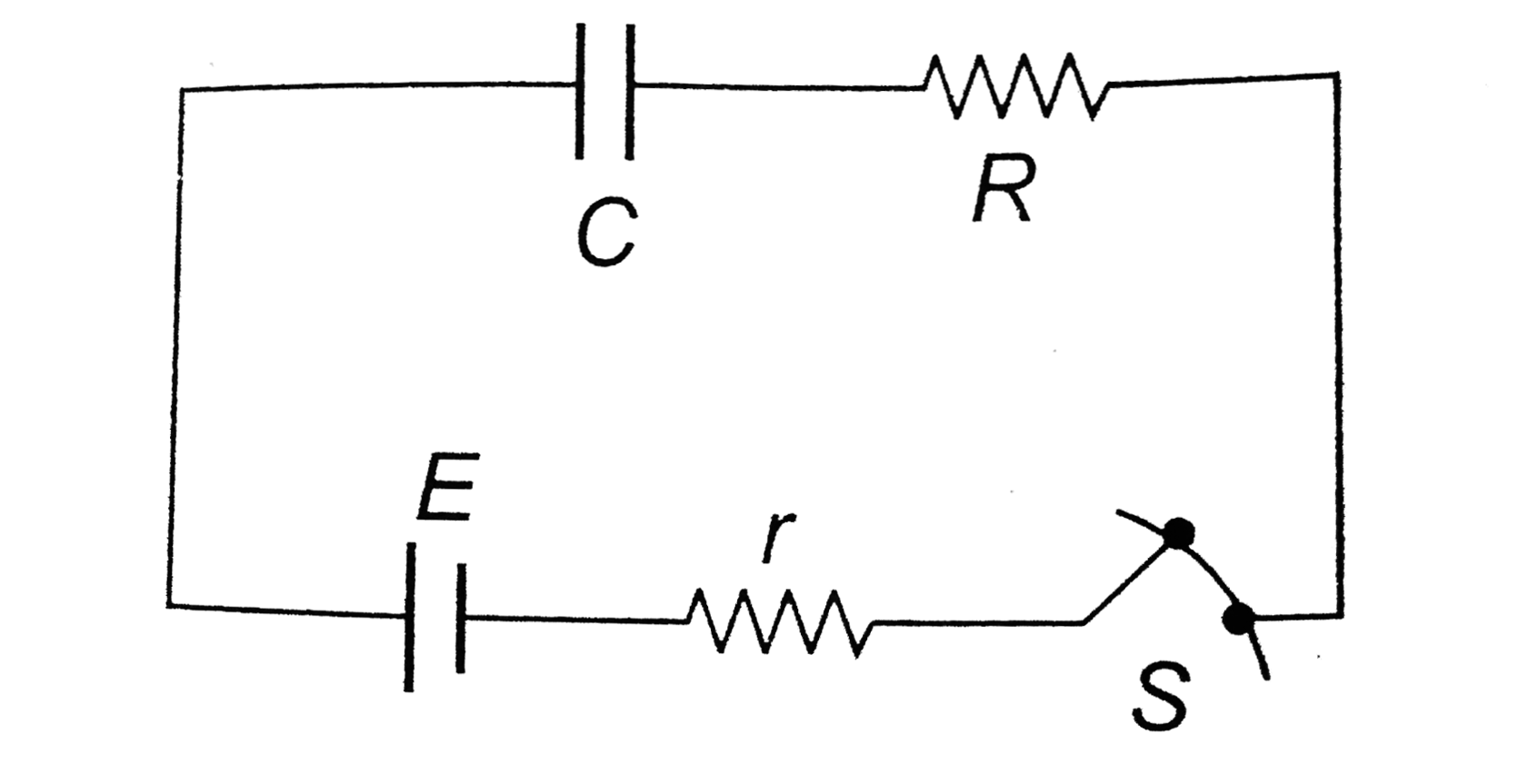
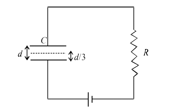
In the given circuit, the capacitor of capacitance C is charged by closing key K at t = 0. Find the time required to charge the capacitor up to the maximum charge for the given circuit, if it were to be charged with the charged with constant initial charging rate at t=0 in the given circuit.
 View Solution
Question 90
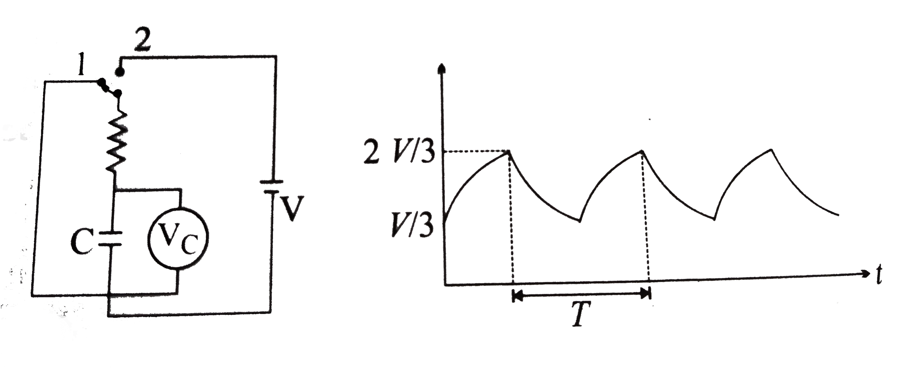
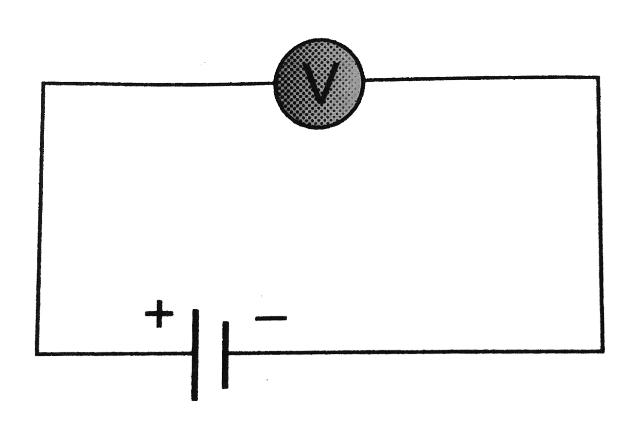
VC is the ideal voltmeter in the figure. Resistance of the resistor shown is R. Initially the switch is in position 2 when charging of the capacitor starts. Initially the capacitor was uncharged. The switch in circuit shifts automatically from 2 to 1 when VC>2V/3 and goes back to 2 from 1 when VC<V/3. The ideal voltmeter reads voltage across capacitor as plotted. What is the period T of the wave from in terms of R and C ?
 ,View Solution
Question 101
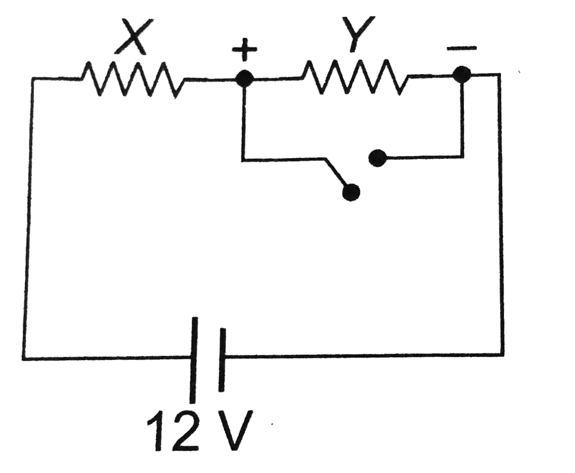
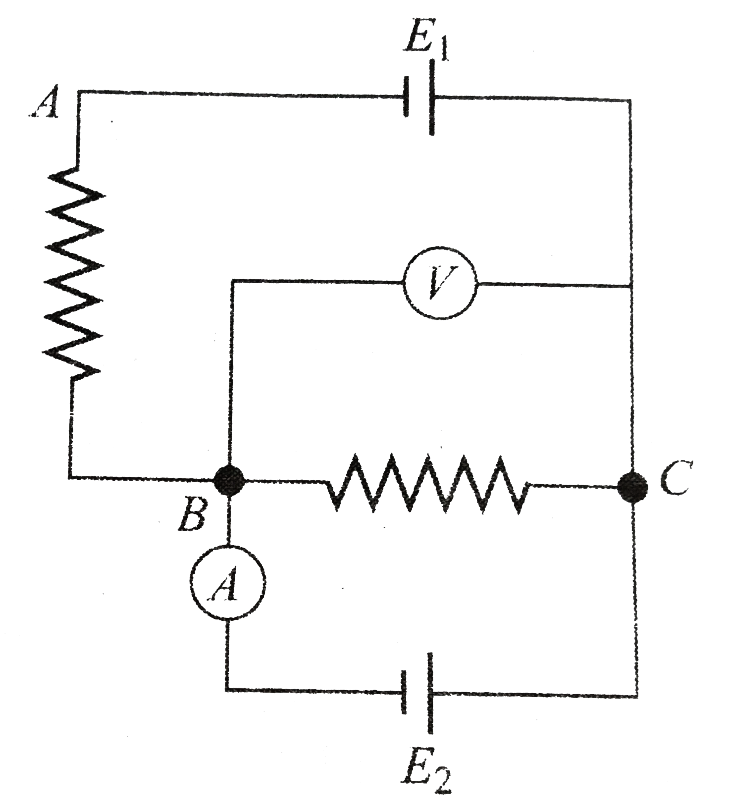
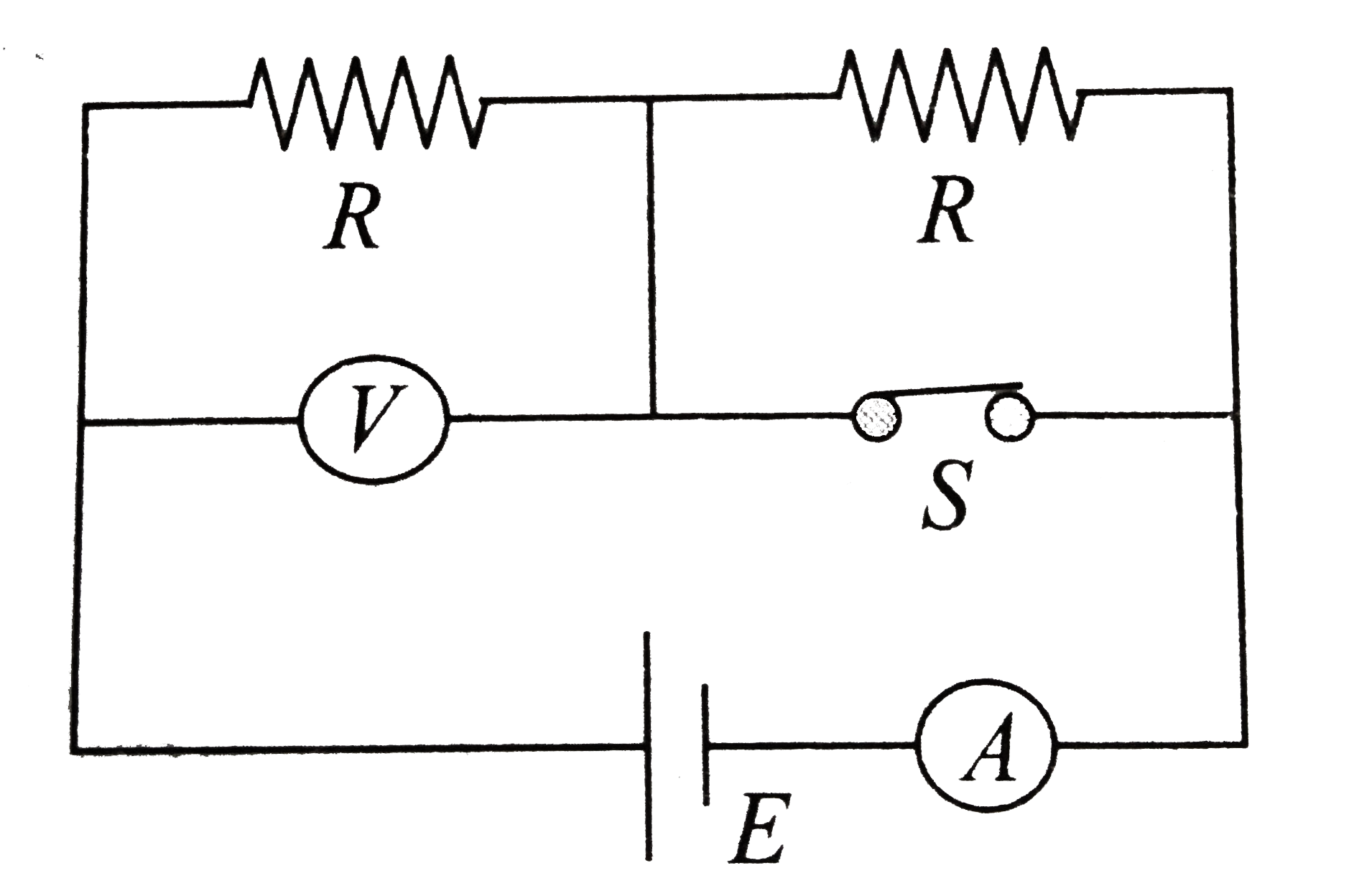
When an ammter of negligible internal resistance is inserted in series with circuit it reads 1A When the voltmeter of very large resistance is connected across X it reads 1V. When the point A and B are shorted by a conducting wire, the voltmeter meausres 10V across the battery. The internal resistance of the battery is equal to
 View Solution
Question 120
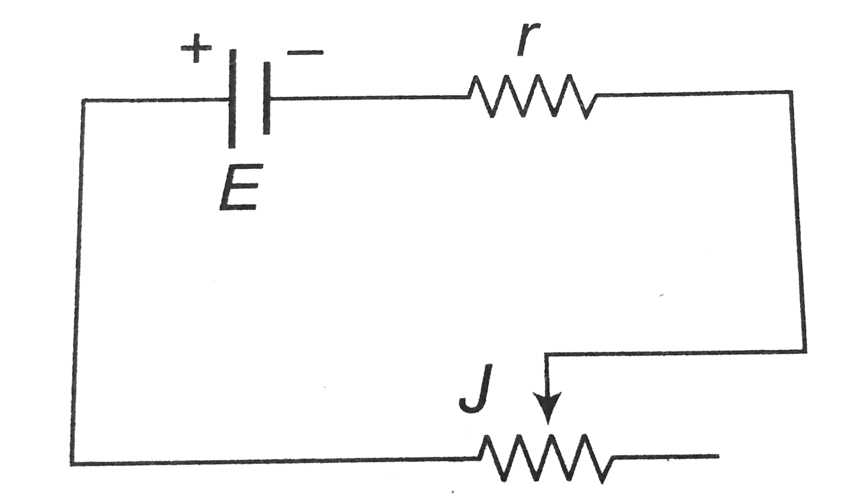
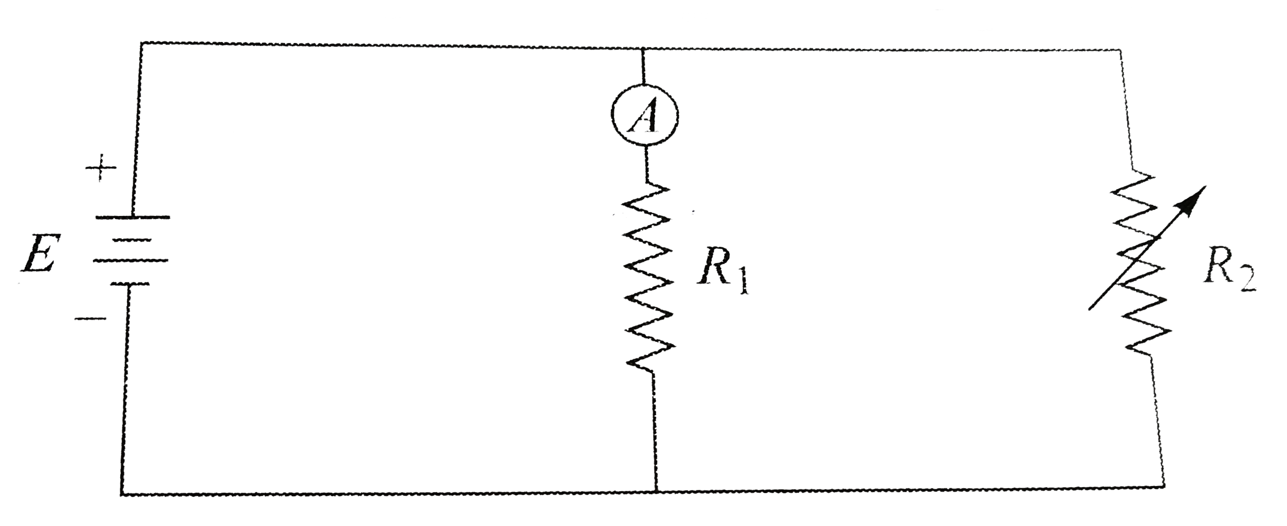
Battery shown in figure has e.m.f. E and internal resistance r. Current in the circuit can be varied by sliding the contact J. If at any instant current flowing through the circuit is I, potential difference between terminals of the cells is V, thermal power generated in the cell is equal to η fraction of total electrical power generated in it, then which of the following graphs is correct ?
 View Solution
Question 129
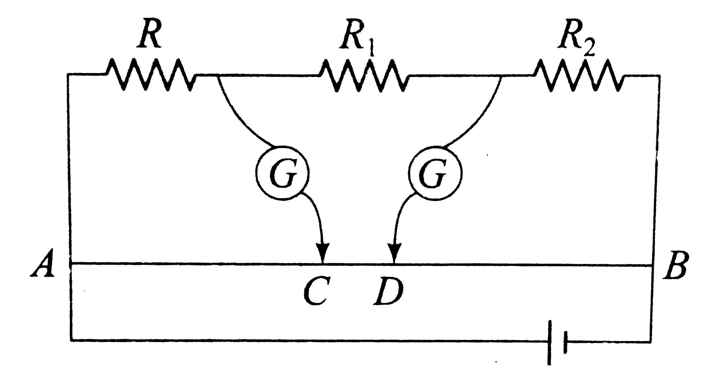
The diagram shows a modified meter bridge, which is used for measuring two unknown resistances at the same time. When only the first galvanometer is used, for obtaining the balance point, it is found at point C. Now the second galvanometer is used, which gives balance point at D. Using the details given in the diagram, find out the value of R1andR2 .
 View Solution
Question 148
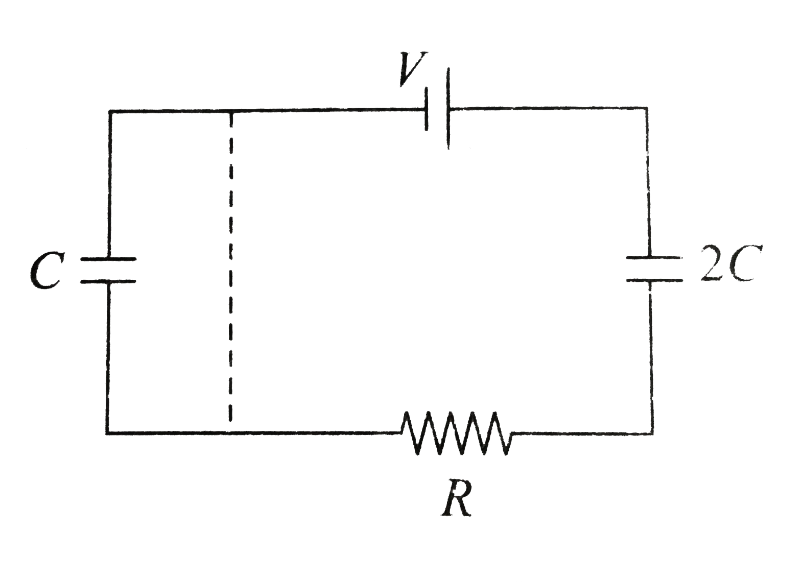
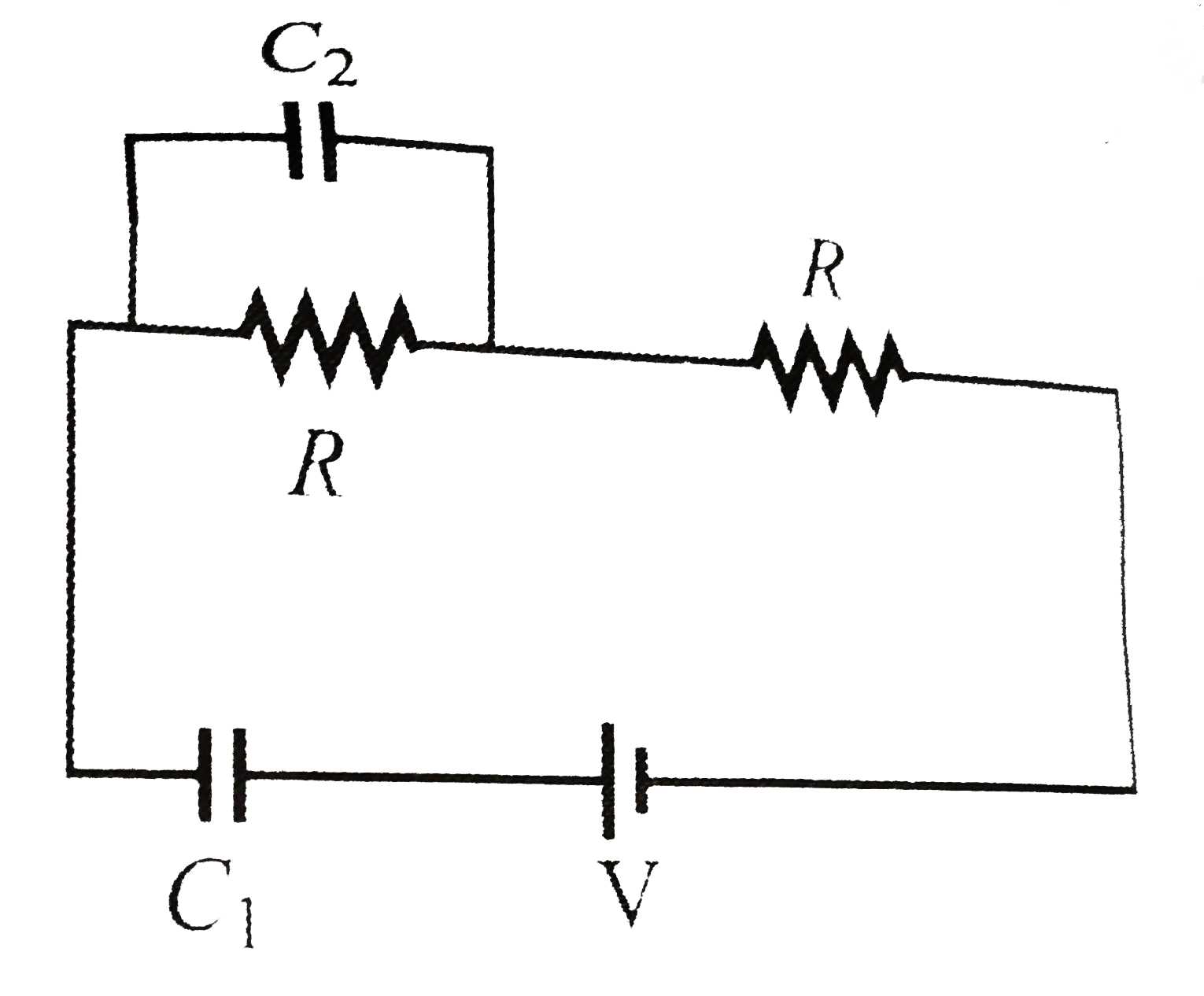
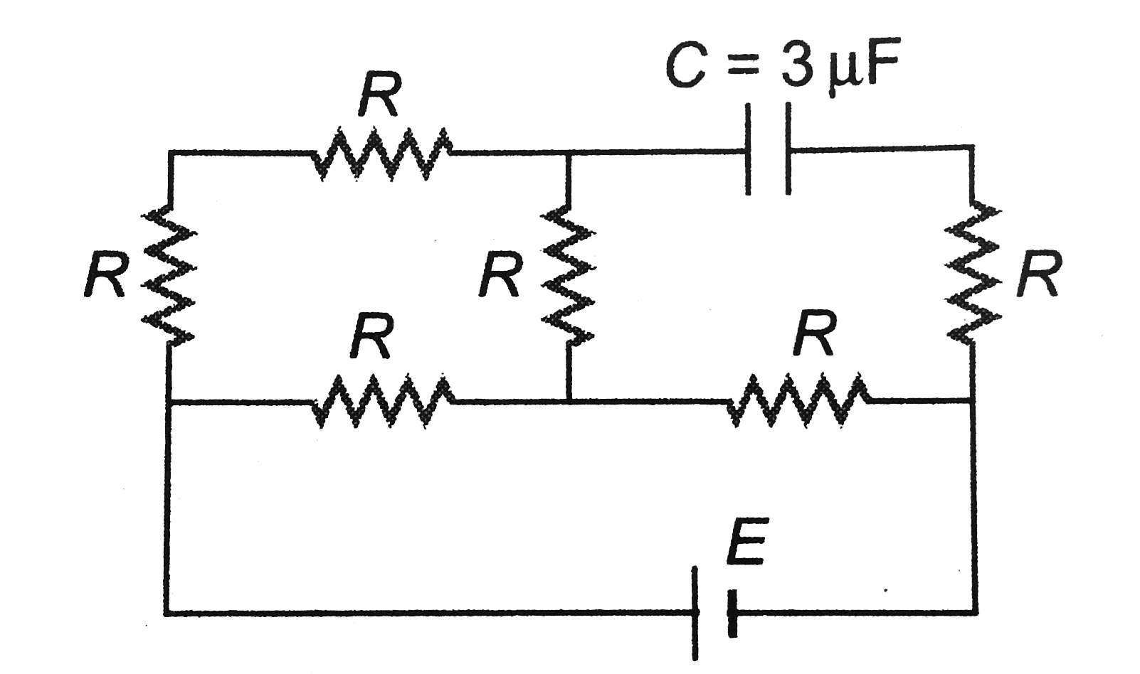
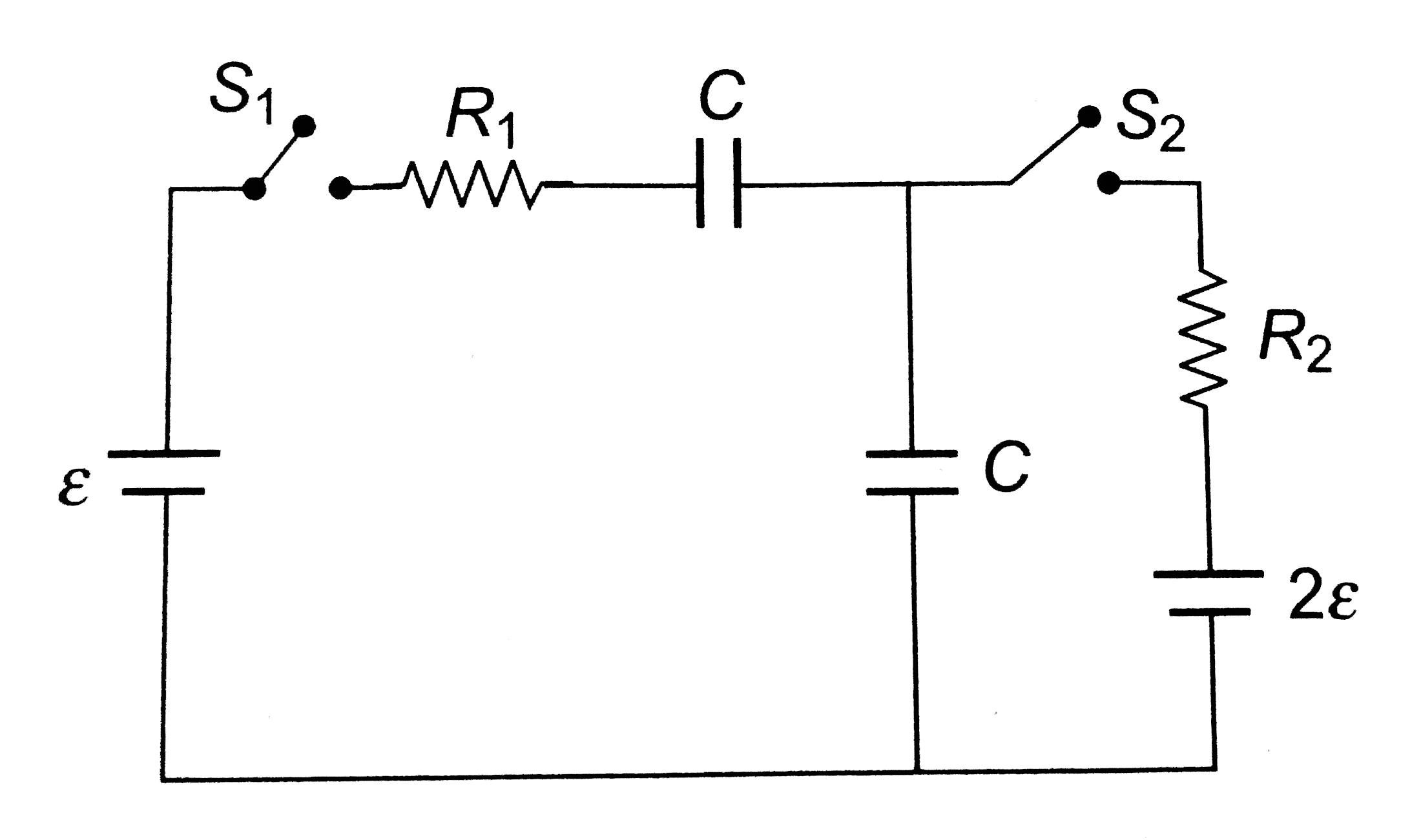
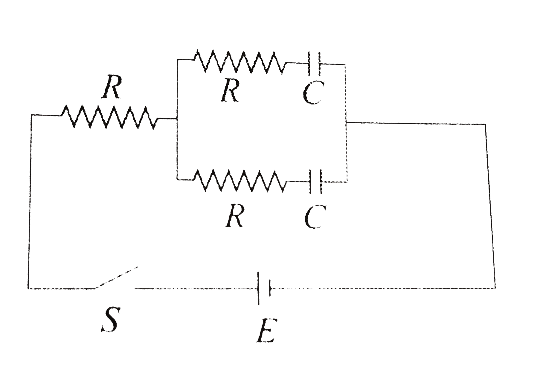
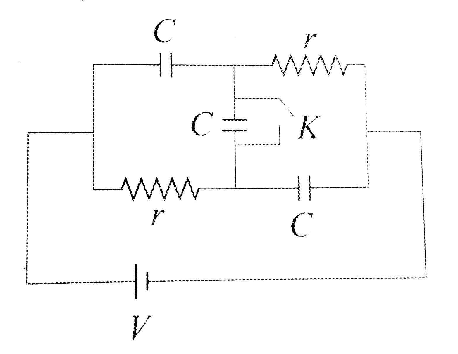
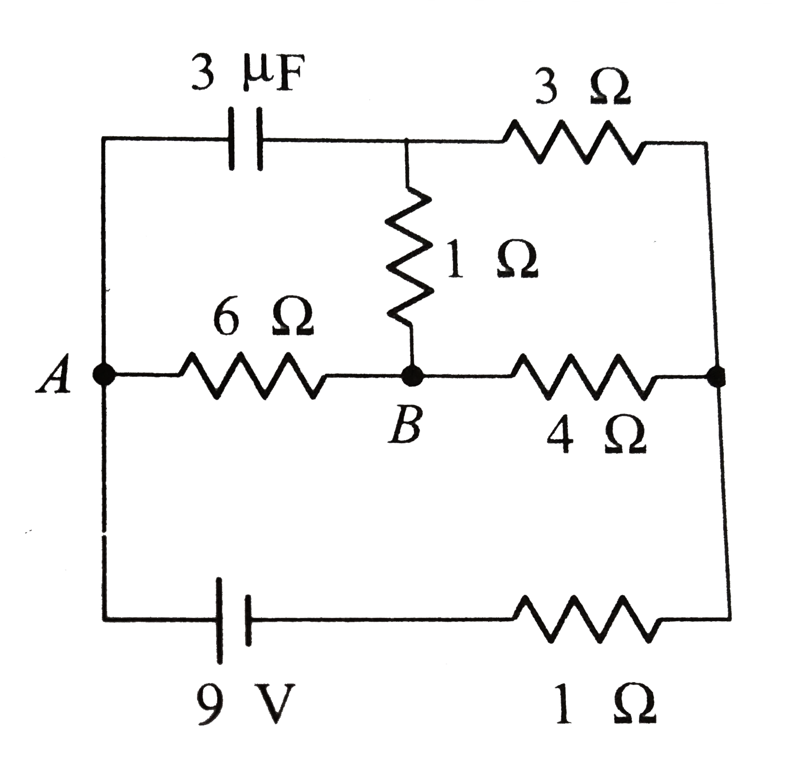
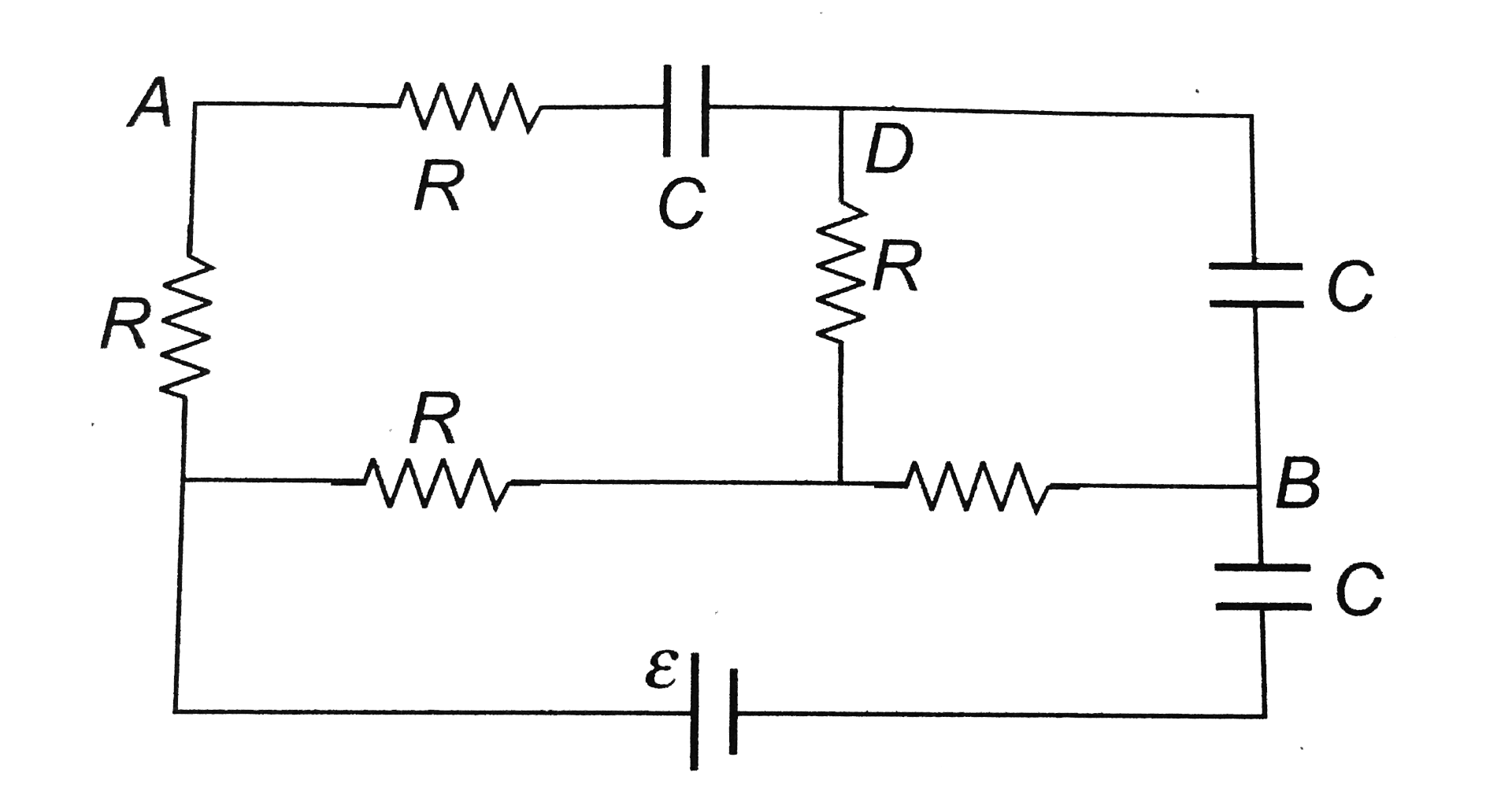
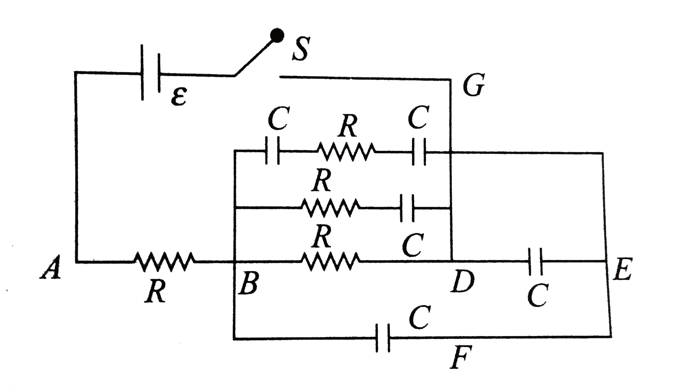
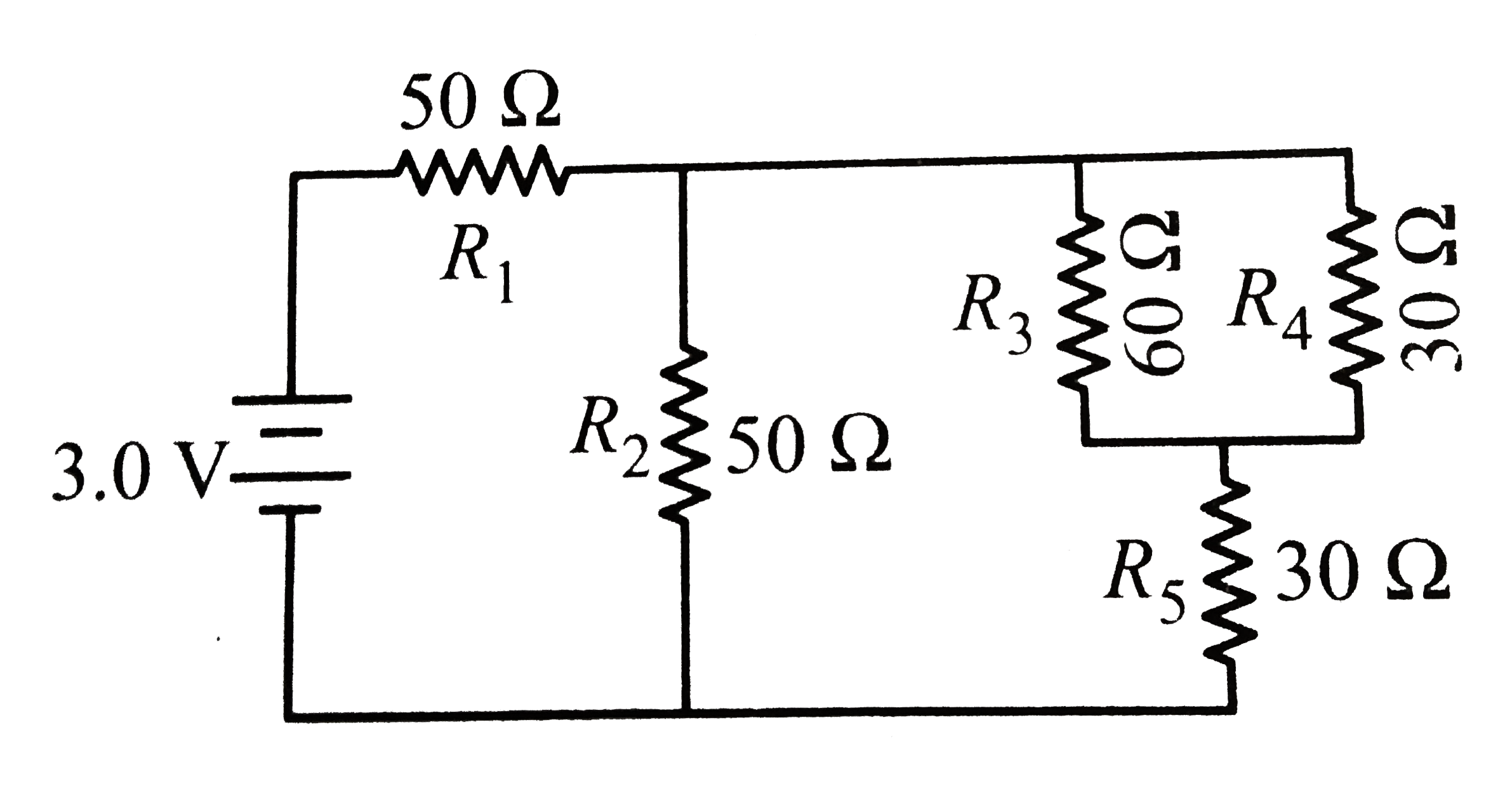
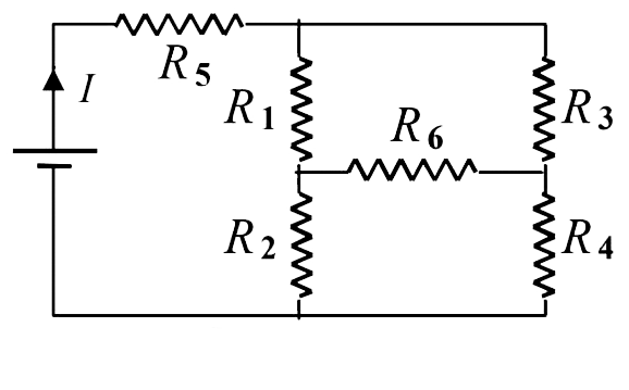
A series circuit consists of two capacitors, a resistors, and an ideal voltage source. The circuit is initially at steady state. Now a conducting wire is shorted across the capacitor C as shown by dotted line. After shorting the wire, select the correct statement// statements.
 View Solution
Question 155
Statement I: If an electric field is applied to a metallic conductor, the free electrons experience a force but do not accelerate, they only drift at a constant speed.
Statement II: The force exerted by the electric field is completely balanced by the Coulomb force between electrons and protons . View SolutionQuestion 156
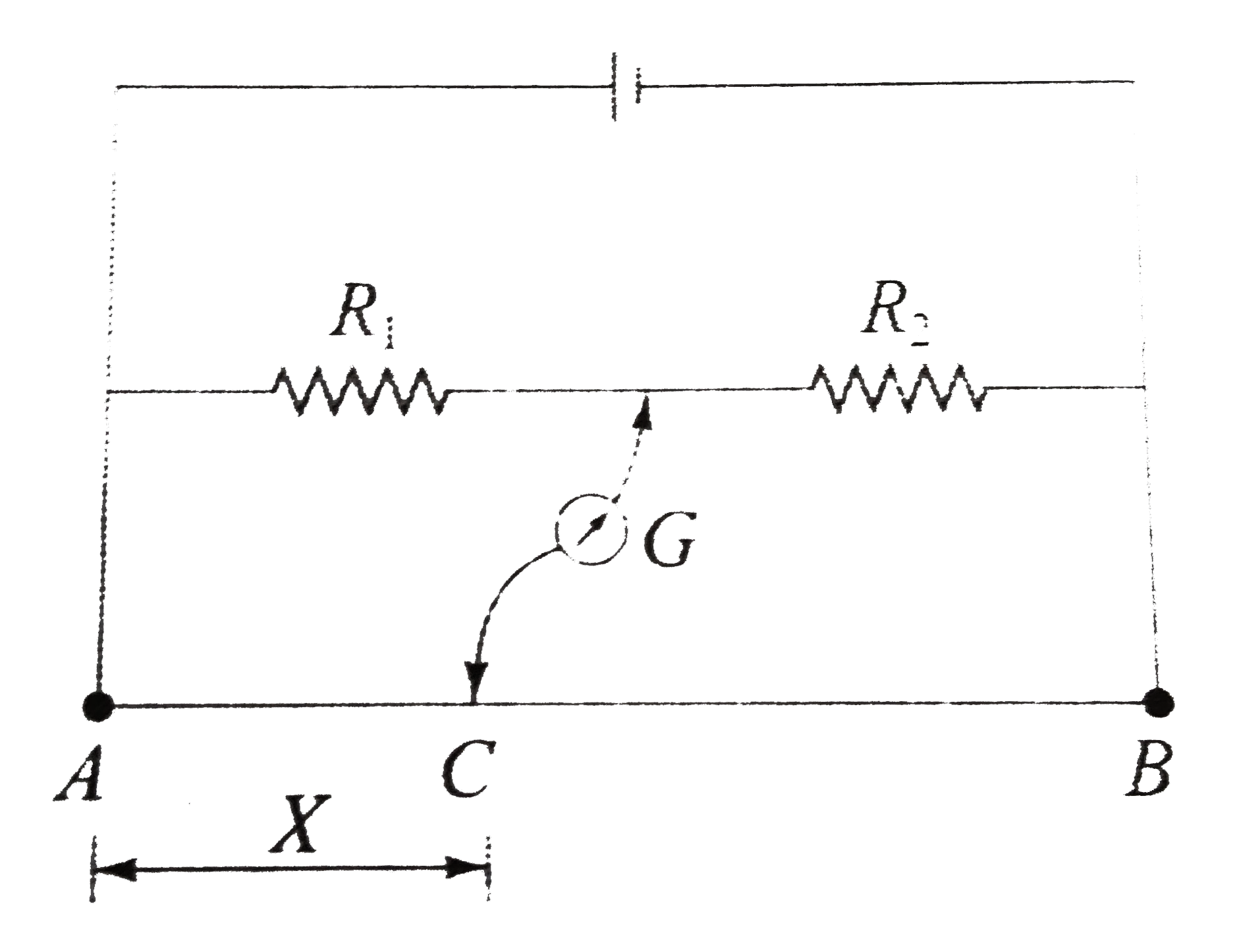
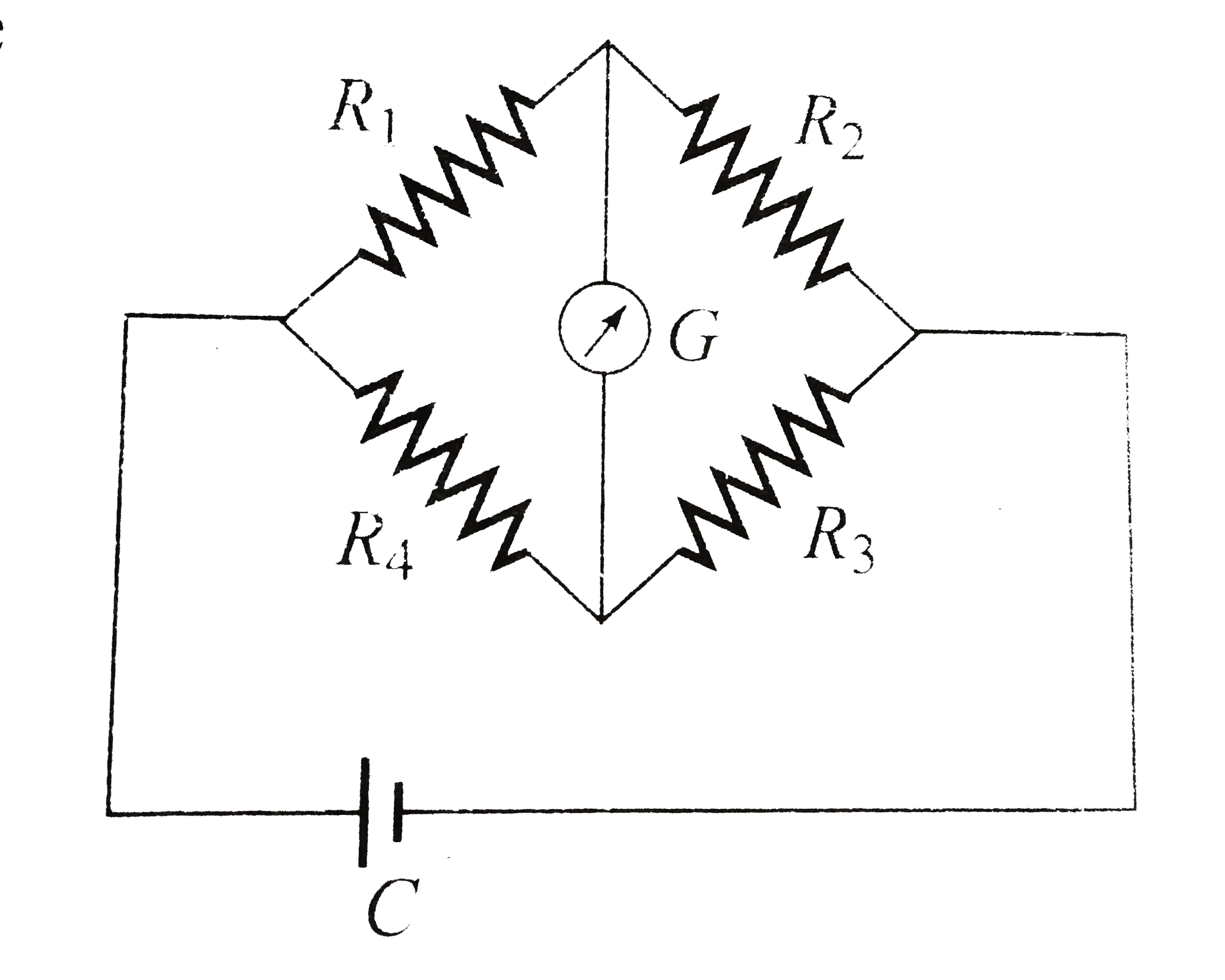
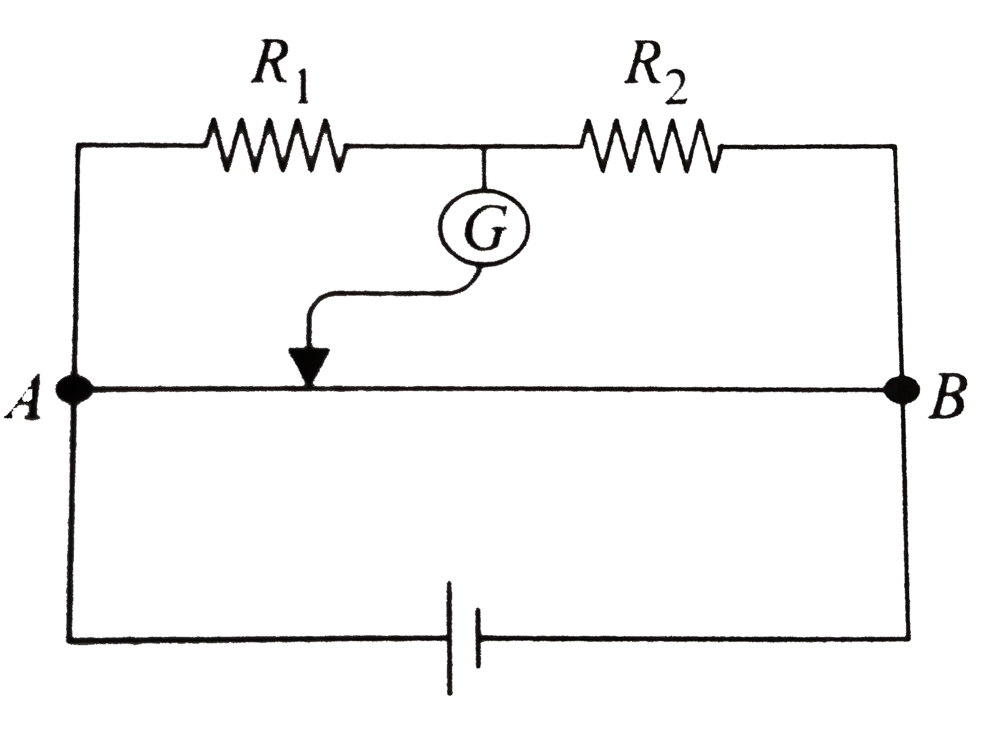
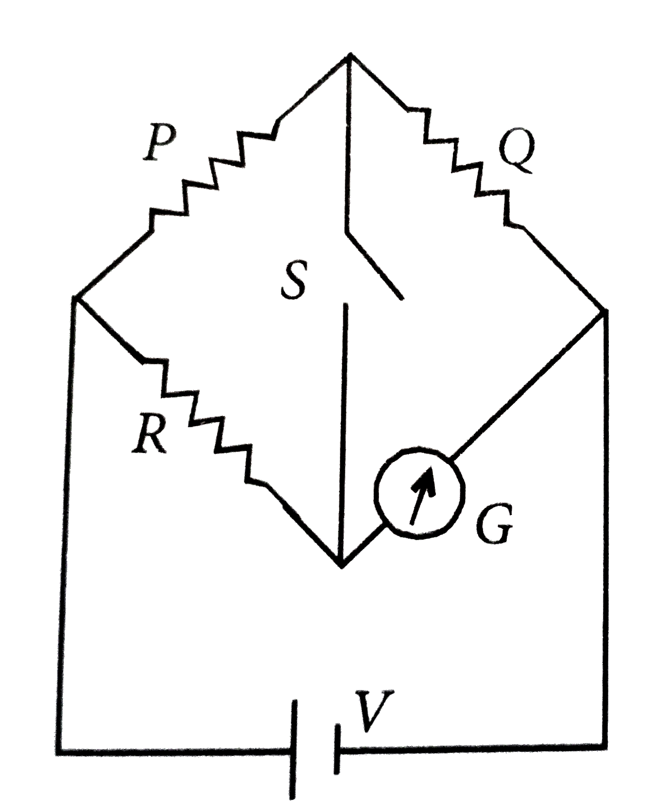
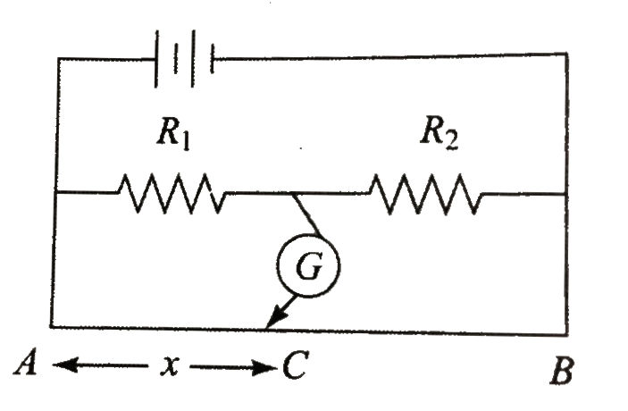
Statement I: In the meter bridge experiment shown in figure, the balance length AC corresponding to null deflection of the galvanometer is x. If the radius of the wire AB is doubled, the balanced length becomes 4x.
Statement II: The resistance of a wire is inversely proportional to the square of its radius.
 View Solution
Question 157
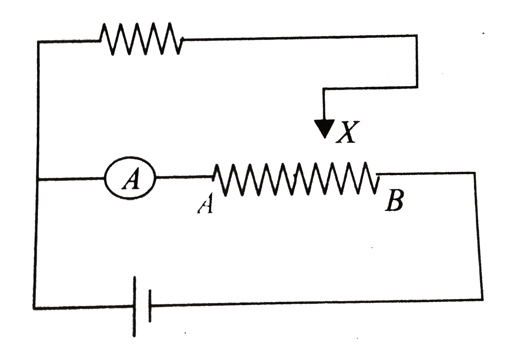
Statement I: In the potentiometer circuit shown in figure. E1andE2 are the emf of cells C1andC2, repsectively, with E1>E2. Cell C1 has negligible internal resistance. For a given resistor R, the balance length is x. If the diameter of the potentiometer wire AB is increased, the balance length x will decrease.
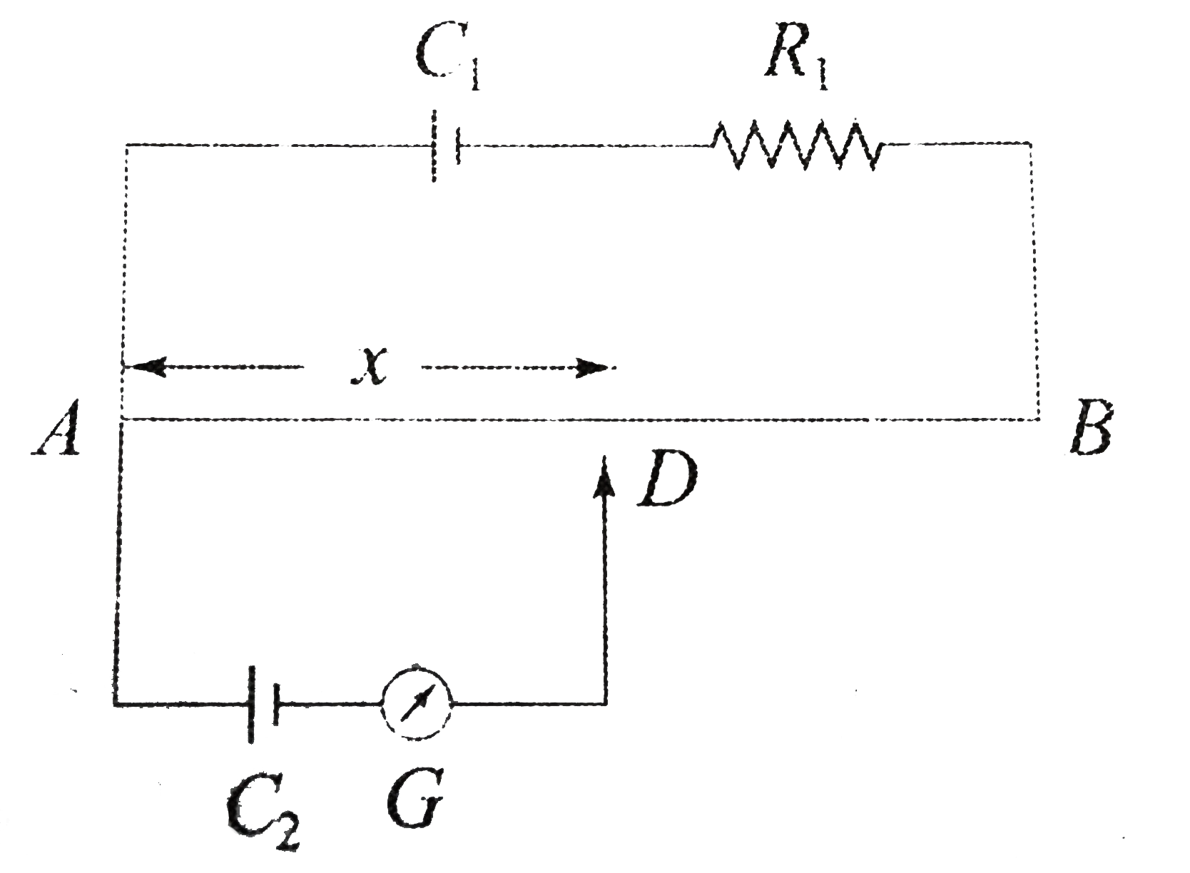
Statement II: At the balance point, the potential difference between AD due to cell C1isE2 , the emf of cell C2. View SolutionQuestion 158
Statement I: When an external resistor of resistance R (connected across a cell to internal resistance r ) is varied, power consumed by resistance R is maximum when R = r.
Statement II: Power consumed by a resistor of constant resistance R is maximum when current through it is maximum. View SolutionQuestion 160
Statement I: A wire of uniform cross-section and uniform resistivity is connected across an ideal cell. Now the length of the wire is doubled keeping volume of the wire constant. The drift velocity of electrons after stretching the wire becomes one-fouth of what it was before stretching the wire.
Statement II: If a wire (of uniform resistivity and uniform cross section) of length l0 is stretched to length nl0, then its resistance becomes n2 times of what it was before stretching the wire (the volume of wire is kept constant in stretching process). Further at constant potential difference, current is inversely proportional to resistance. Finally, drift velocity of free electron is directly proportional to current and inversely proportional to cross-sectional area of current carrying wire. View SolutionQuestion 163
Ram ans Shyam purchased two electric tea kettles A and B of same size, same thickness, and same volume of 0.4L. They studied the specification of kettles as under
Ke≤A:
specific heat capacity =1680Jkg−1K−1
Mass = 200 g
Cost = Rs. 400
Kettle B:
Specific heat capacity = 2450Jkg−1K−1
Mass = 400 g
Cost = Rs. 400
When kettle A is switched on with constant potential source, the tea begins to boil in 6 min. When kettle B is switched on with the same source separately, then tea begins to boil in 8 min. The efficiengy of kettle is defined as
(Energy used for liquid heating)/(Total energy supplied)
They made discussion on specification and efficiency of kettles and subsequently prepared a list of questions to draw the conclusions. Some of them are as under (assume specific heat of tea liquid as 4200Jkg−1K−1 and density 1000kgm−3
Efficiency of kettle A is View SolutionQuestion 164
Ram ans Shyam purchased two electric tea kettles A and B of same size, same thickness, and same volume of 0.4L. They studied the specification of kettles as under
Ke≤A:
specific heat capacity =1680Jkg−1K−1
Mass = 200 g
Cost = Rs. 400
Kettle B:
Specific heat capacity = 2450Jkg−1K−1
Mass = 400 g
Cost = Rs. 400
When kettle A is switched on with constant potential source, the tea begins to boil in 6 min. When kettle B is switched on with the same source separately, then tea begins to boil in 8 min. The efficiengy of kettle is defined as
(Energy used for liquid heating)/(Total energy supplied)
They made discussion on specification and efficiency of kettles and subsequently prepared a list of questions to draw the conclusions. Some of them are as under (assume specific heat of tea liquid as 4200Jkg−1K−1 and density 1000kgm−3
Efficiency of kettle B is . View SolutionQuestion 165
Ram and Shyam purchased two electric tea kettles A and B of same size, same thickness, and same volume of 0.4L. They studied the specification of kettles as under
Ke≤A:
specific heat capacity =1680Jkg−1K−1
Mass = 200 g
Cost = Rs. 400
Kettle B:
Specific heat capacity = 2450Jkg−1K−1
Mass = 400 g
Cost = Rs. 400
When kettle A is switched on with constant potential source, the tea begins to boil in 6 min. When kettle B is switched on with the same source separately, then tea begins to boil in 8 min. The efficiengy of kettle is defined as
(Energy used for liquid heating)/(Total energy supplied)
They made discussion on specification and efficiency of kettles and subsequently prepared a list of questions to draw the conclusions. Some of them are as under (assume specific heat of tea liquid as 4200Jkg−1K−1 and density 1000kgm−3
Ratio of efficiency consumed charges for one time boiling of tea in kettle A to that in kettle B is View SolutionQuestion 166
Ram ans Shyam purchased two electric tea kettles A and B of same size, same thickness, and same volume of 0.4L. They studied the specification of kettles as under
Ke≤A:
specific heat capacity =1680Jkg−1K−1
Mass = 200 g
Cost = Rs. 400
Kettle B:
Specific heat capacity = 2450Jkg−1K−1
Mass = 400 g
Cost = Rs. 400
When kettle A is switched on with constant potential source, the tea begins to boil in 6 min. When kettle B is switched on with the same source separately, then tea begins to boil in 8 min. The efficiengy of kettle is defined as
(Energy used for liquid heating)/(Total energy supplied)
They made discussion on specification and efficiency of kettles and subsequently prepared a list of questions to draw the conclusions. Some of them are as under (assume specific heat of tea liquid as 4200Jkg−1K−1 and density 1000kgm−3
If resistances of coil of kettles A and B are RAandRB, respectively, then we can say View SolutionQuestion 167
Ram ans Shyam purchased two electric tea kettles A and B of same size, same thickness, and same volume of 0.4L. They studied the specification of kettles as under
Ke≤A:
specific heat capacity =1680Jkg−1K−1
Mass = 200 g
Cost = Rs. 400
Kettle B:
Specific heat capacity = 2450Jkg−1K−1
Mass = 400 g
Cost = Rs. 400
When kettle A is switched on with constant potential source, the tea begins to boil in 6 min. When kettle B is switched on with the same source separately, then tea begins to boil in 8 min. The efficiengy of kettle is defined as
(Energy used for liquid heating)/(Total energy supplied)
They made discussion on specification and efficiency of kettles and subsequently prepared a list of questions to draw the conclusions. Some of them are as under (assume specific heat of tea liquid as 4200Jkg−1K−1 and density 1000kgm−3
If both the kettles are joined with the same source in series one after the other, then boiling starts in kettle A and kettle B after View SolutionQuestion 168
Electric fuse is a protective device used in series with an electric circuit or an electric appliance to save it from damage due to overheating porduced by strong current in the circuit or application. Fuse wire is generally made from an alloy of lead and tin, which has hifh resistance and low melting point. It is connected in series in an electric installation. If a circuit gets accidentally short-circuited, a large current flows, then fuse wire melts away, which causes a break in the circuit. The power through fuse (F') is equal to heat energy lost per unit area per unit time (h) (neglecting heat loses from ends of the wire).
P=I2R=h×2πrl[R=ρlπr2]
where r and l are the length and radius of fuse wire, respectively.
A Battery is described by its emf (E) and internal resistance (r). Efficiency of battery (η) is defined as the ratio of the output to the input power.
η=OutputpowerInputpower×100%
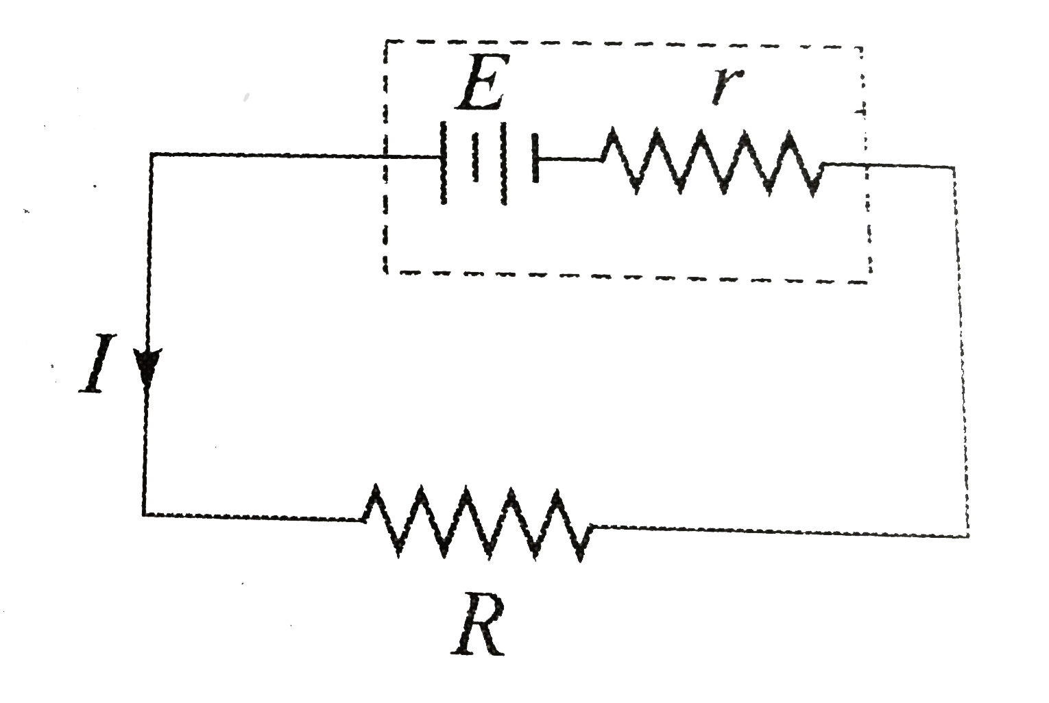
But I=E/(R+r), input power = EI.
Output power =EI−I2r, then.
η=(EI−I2rEI)×100=(1−IrE)×100
=[1−(ER+r)(rE)]×100=(RR+r)×100
We know that output power of a source is maximum when the external resistance is equal to internal resistance, i.e., R = r .
Two fuse wires of same potential , material have length ratio 1:2 and ratio of radius 4:1. Then respective ratio of their current rating will be View SolutionQuestion 169
Electric fuse is a protective device used in series with an electric circuit or an electric appliance to save it from damage due to overheating porduced by strong current in the circuit or application. Fuse wire is generally made from an alloy of lead and tin, which has hifh resistance and low melting point. It is connected in series in an electric installation. If a circuit gets accidentally short-circuited, a large current flows, then fuse wire melts away, which causes a break in the circuit. The power through fuse (F') is equal to heat energy lost per unit area per unit time (h) (neglecting heat loses from ends of the wire).
P=I2R=h×2πrl[R=ρlπr2]
where r and l are the length and radius of fuse wire, respectively.
A Battery is described by its emf (E) and internal resistance (r). Efficiency of battery (η) is defined as the ratio of the output to the input power.
η=OutputpowerInputpower×100%
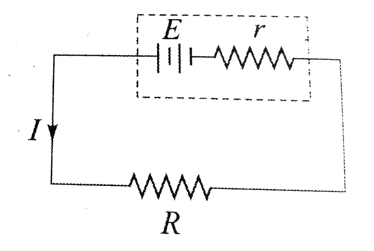
But I=E/(R+r), input power = EI.
Output power =EI−I2r, then.
η=(EI−I2rEI)×100=(1−IrE)×100
=[1−(ER+r)(rE)]×100=(RR+r)×100
We know that output power of a source is maximum when the external resistance is equal to internal resistance, i.e., R = r .
The maximum power rating of a 20.0Ω fuse wire is 2.0kW. This fuse wire can be connected safely to a DC source (negligible internal resistance) of View SolutionQuestion 170
Electric fuse is a protective device used in series with an electric circuit or an electric appliance to save it from damage due to overheating porduced by strong current in the circuit or application. Fuse wire is generally made from an alloy of lead and tin, which has hifh resistance and low melting point. It is connected in series in an electric installation. If a circuit gets accidentally short-circuited, a large current flows, then fuse wire melts away, which causes a break in the circuit. The power through fuse (F') is equal to heat energy lost per unit area per unit time (h) (neglecting heat loses from ends of the wire).
P=I2R=h×2πrl[R=ρlπr2]
where r and l are the length and radius of fuse wire, respectively.
A Battery is described by its emf (E) and internal resistance (r). Efficiency of battery (η) is defined as the ratio of the output to the input power.
η=OutputpowerInputpower×100%
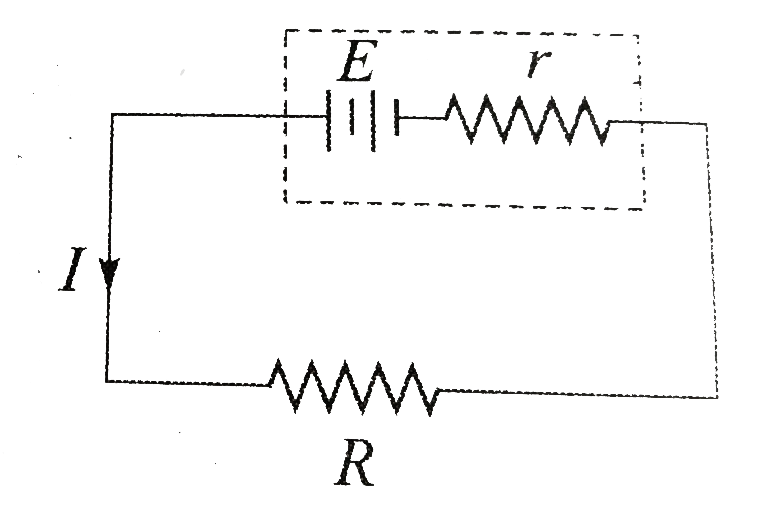
But I=E/(R+r), input power = EI.
Output power =EI−I2r, then.
η=(EI−I2rEI)×10(1−IrE)×100
=1−(ER+r)(rE)×100=(RR+r)×100
We know that output power of a source is maximum when the external resistance is equal to internal resistance, i.e., R = r .
Efficiency of a battery (nonideal) when delivering the maximum power is View SolutionQuestion 171
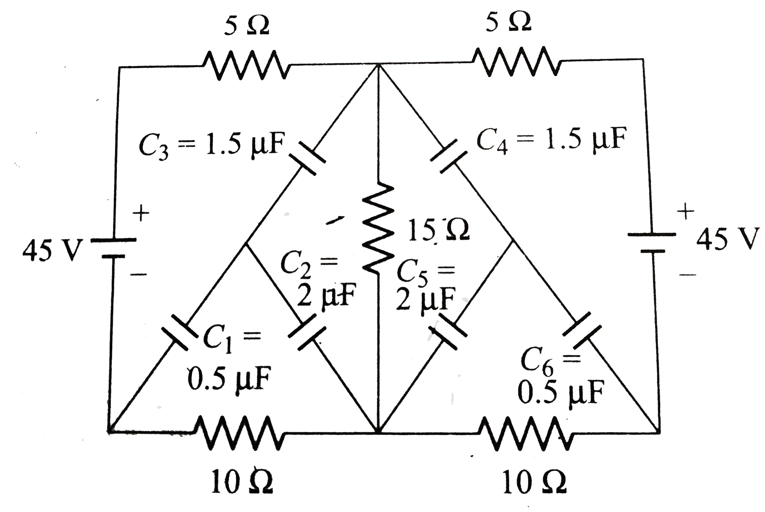
In the connection shown in the figure, initially the switch K is open and the capacitor is uncharged. Then the switch is closed, and the capacitor is charged up to the steady state and the switch is opened again. Determine the values indicated by the values indicated by the ammeter just after closing the switch
[GivenV0=30V,R1=10kΩ,R2=5kΩ]
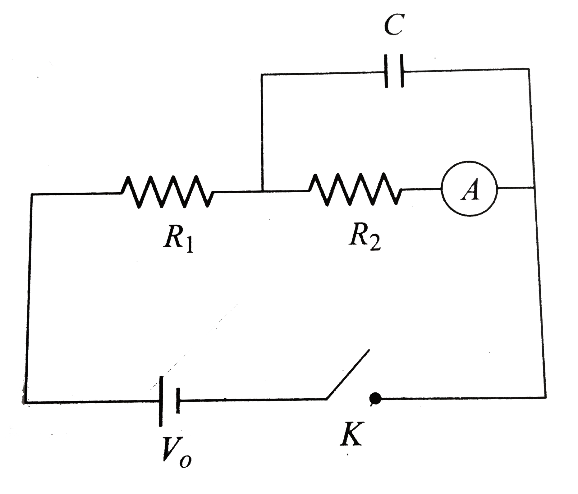 .
.
A long time after switch was closed.View SolutionQuestion 172
In the connecting shows in Fig. 6.68, intially swich K is open and the capacitor is uncharged. Then the switch is closed and the capacitor is changed up to the steady state and the switch is opened again. Determine the values indicated by thee ammeter.
(Given : V0=30V, R1=10kΩ,

A long time after the swich was closedView SolutionQuestion 173
In the connection shown in the figure, initially the switch K is open and the capacitor is uncharged. Then the switch is closed, and the capacitor is charged up to the steady state and the switch is opened again. Determine the values indicated by the values indicated by the ammeter just after closing the switch
[GivenV0=30V,R1=10kΩ,R2=5kΩ]
 .
.
A long time after switch was closed.View SolutionQuestion 174
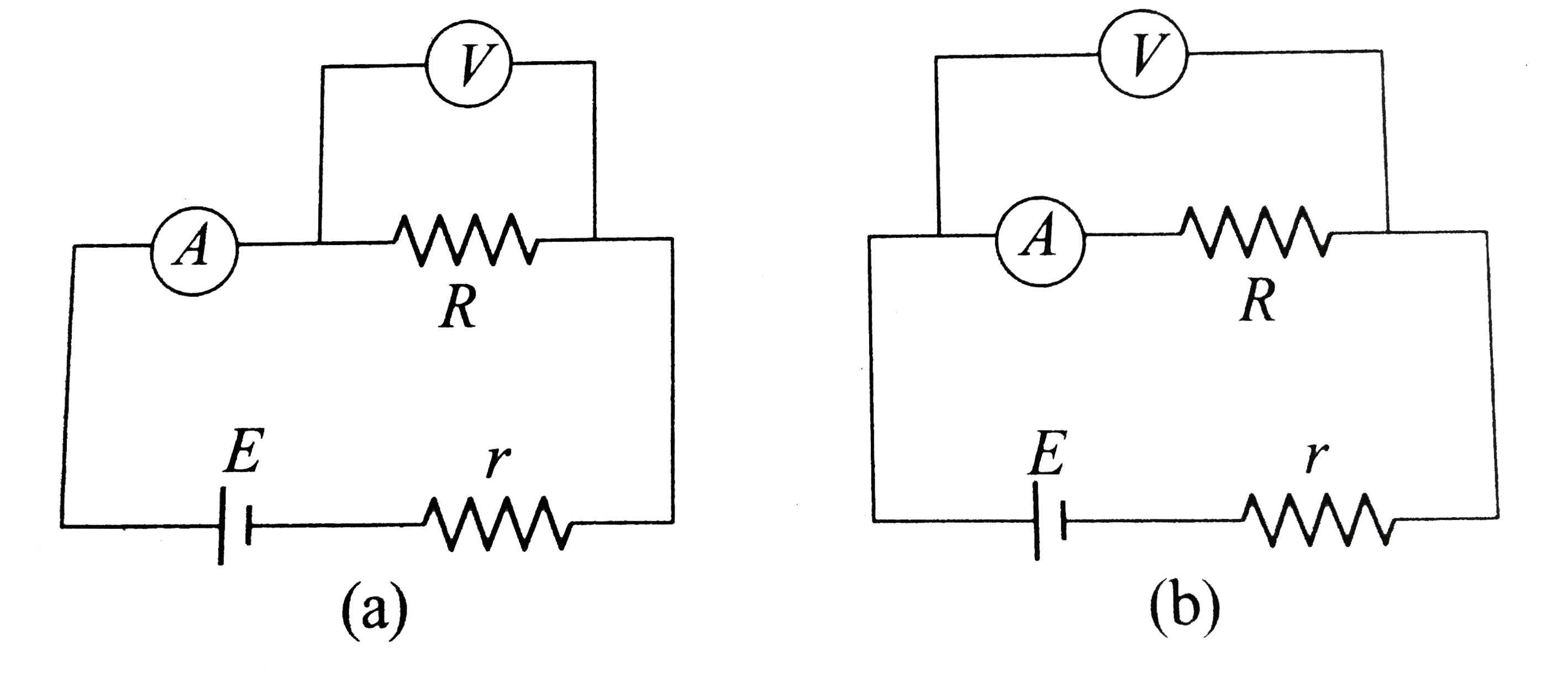
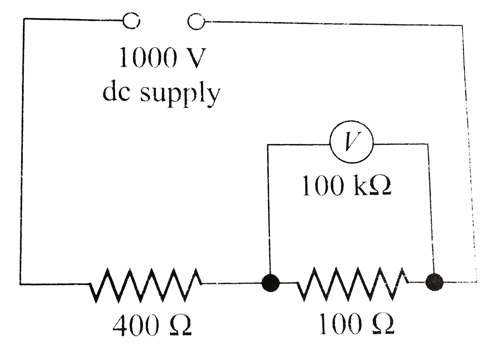
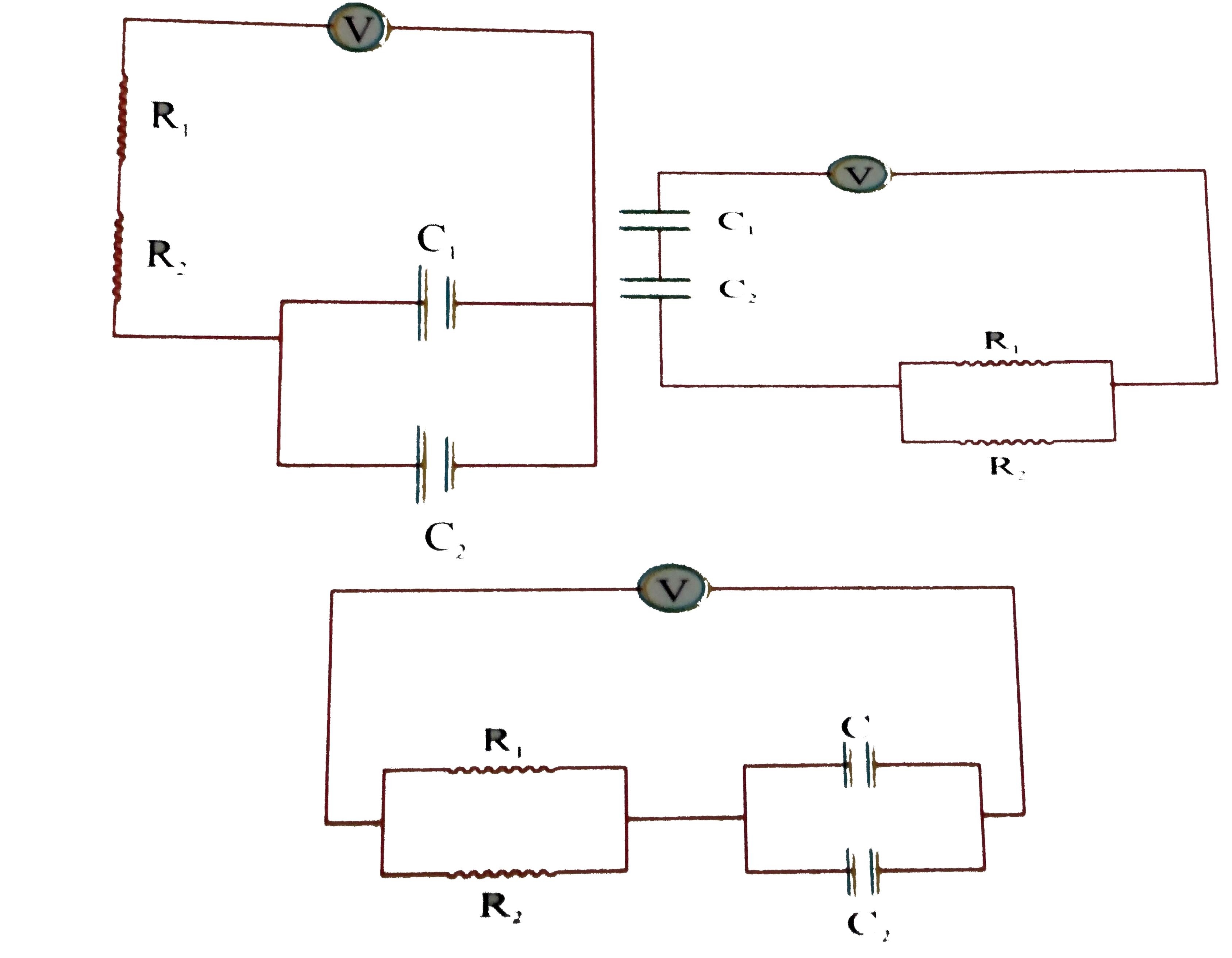
The value of resistance of an unknown resistor is calculated using the formula R=V/I where V and I are the readings of the voltmeter and the ammeter, respectivley. Consider the circuits below. The internal resistances of the voltmeter and the ammeter (RVandRG,respectively) are finite and nonzero.
 ,
,
Let RAandRB be the calculated values in the two cases A and B , respectively.
If the resistance of voltmeter is RV=1kΩ and the percentage error in the measurement of R (the value of R is nearly 10Ω)is View SolutionQuestion 175
The value of resistance of an unknown resistor is calculated using the formula R=V/I where V and I are the readings of the voltmeter and the ammeter, respectivley. Consider the circuits below. The internal resistances of the voltmeter and the ammeter (RVandRG,respectively) are finite and nonzero.
 ,
,
Let RAandRB be the calculated values in the two cases A and B , respectively.
If the resistance of voltmeter is RV=1kΩ and the percentage error in the measurement of R (the value of R is nearly 10Ω)is View SolutionQuestion 176
The value of resistance of an unknown resistor is calculated using the formula R=V/I where V and I are the readings of the voltmeter and the ammeter, respectivley. Consider the circuits below. The internal resistances of the voltmeter and the ammeter (RVandRG,respectively) are finite and nonzero.
 ,
,
Let RAandRB be the calculated values in the two cases A and B , respectively.
If the resistance of voltmeter is RV=1kΩ and the percentage error in the measurement of R (the value of R is nearly 10Ω)is View SolutionQuestion 177
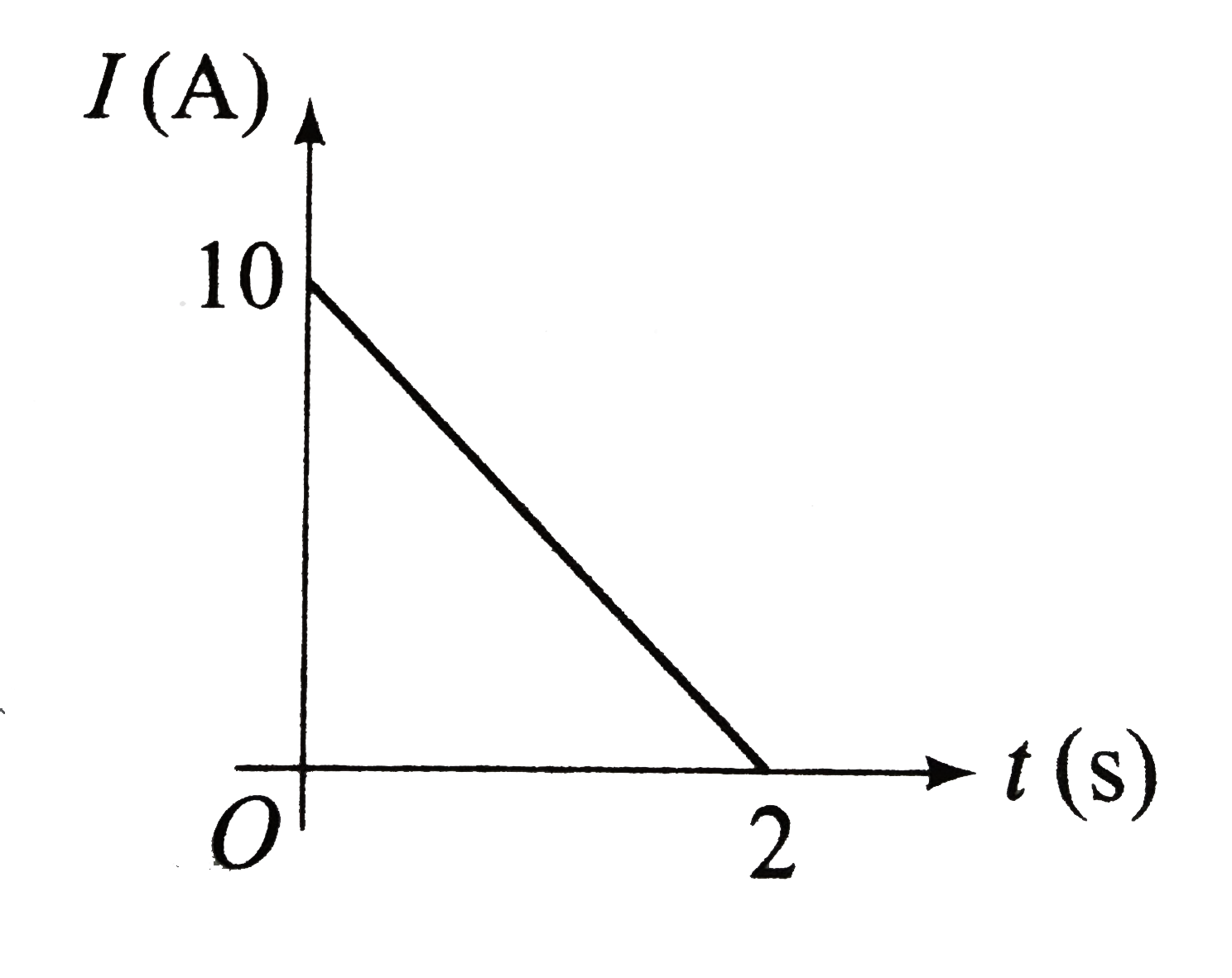
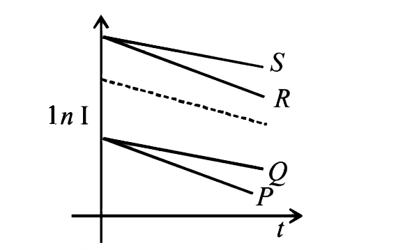
In the circuit given in the figure, both batteries are ideal . Emf E1 of battery 1 has a fixed value, but emf E2 of battery 2 can be varied between 1.0Vand10.0V . The graph gives the currents through the two batteries as a function of E2 but are not marked as which plot corresponds to which battery. But for both plots, current is assumed to be negative when the direction of the current through the battery is opposite to the direction of that battery's emf (direction of emf is from negative to positive.)
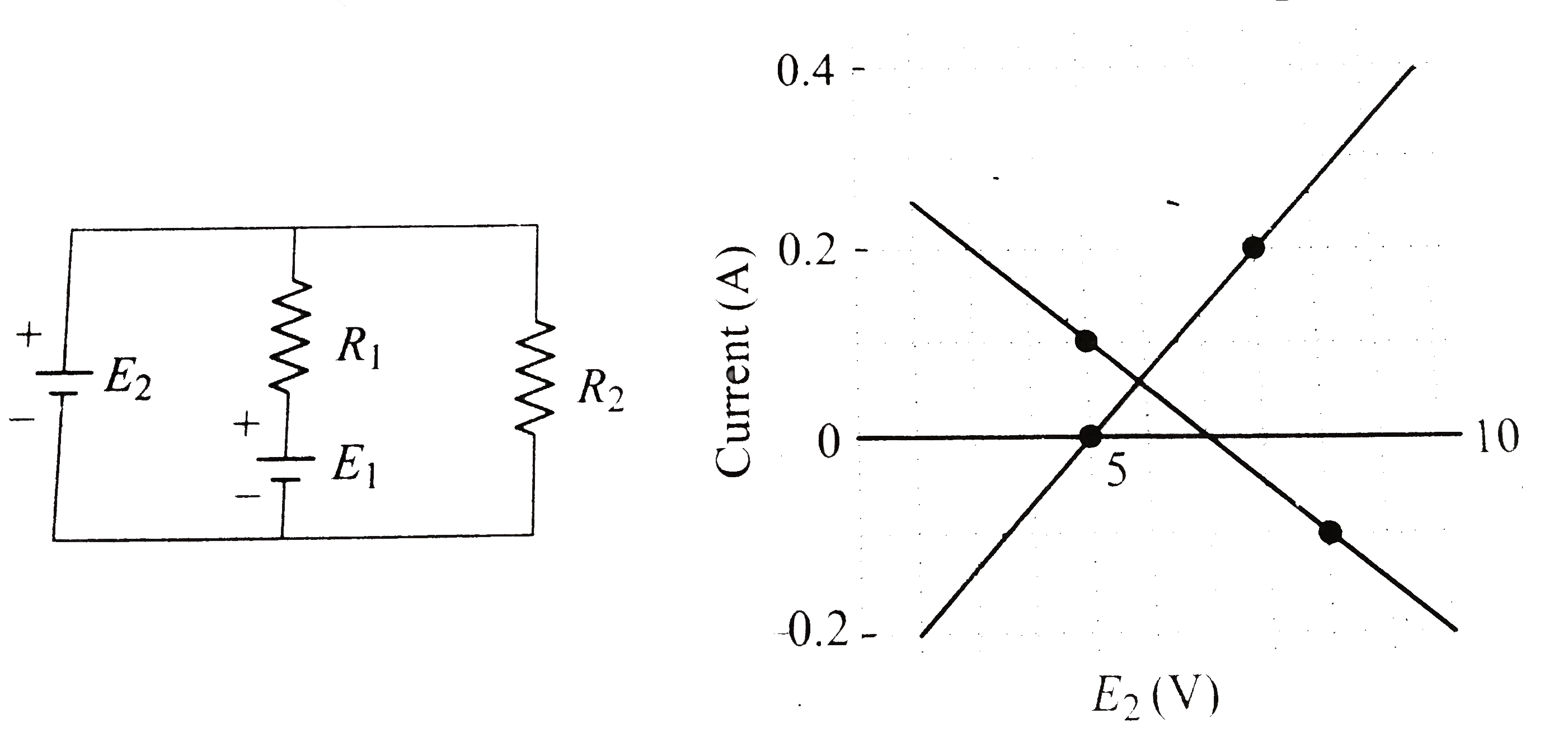
The value of emf E1 is View SolutionQuestion 178
In the circuit given in the figure, both batteries are ideal . Emf E1 of battery 1 has a fixed value, but emf E2 of battery 2 can be varied between 1.0Vand10.0V . The graph gives the currents through the two batteries as a function of E2 but are not marked as which plot corresponds to which battery. But for both plots, current is assumed to be negative when the direction of the current through the battery is opposite to the direction of that battery's emf (direction of emf is from negative to positive.)
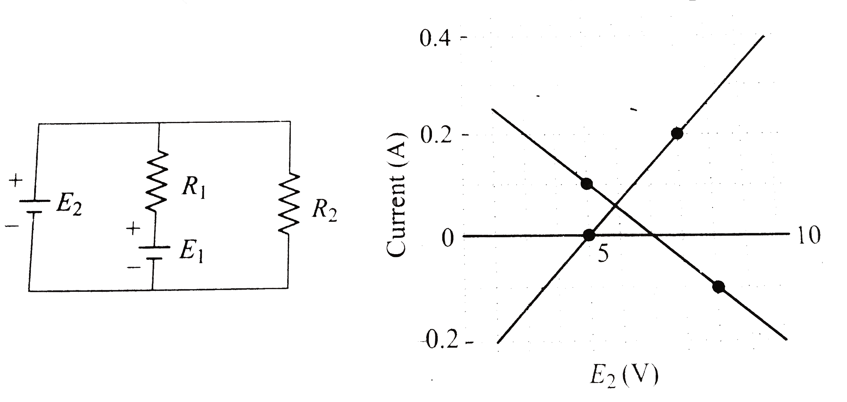 ,
,
The resistance R1 has value View SolutionQuestion 179
In the circuit given in the figure, both batteries are ideal . Emf E1 of battery 1 has a fixed value, but emf E2 of battery 2 can be varied between 1.0Vand10.0V . The graph gives the currents through the two batteries as a function of E2 but are not marked as which plot corresponds to which battery. But for both plots, current is assumed to be negative when the direction of the current through the battery is opposite to the direction of that battery's emf (direction of emf is from negative to positive.)
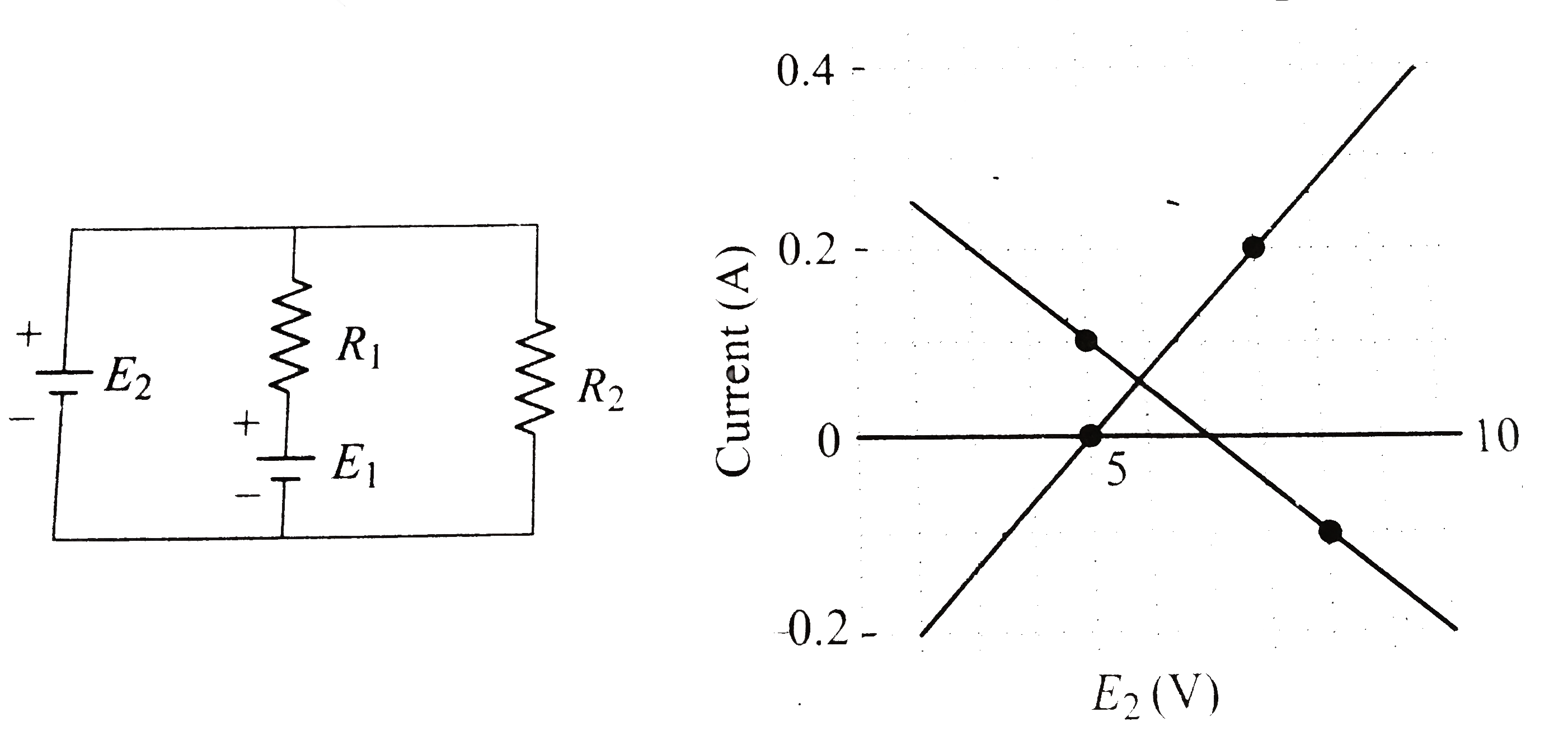 ,
,
The resistance R2 is equal to View SolutionQuestion 188
An ohm meter measures the resistance placed between its leads. This resistance reading is indicated by a galvanometer that operates on current. The ohm meter has an internal source of voltage to create the necessary current to operate the galvanometer and also has approproate resistor to allow just right amount of current through galvanometer. A simple ohm meter is shown here.
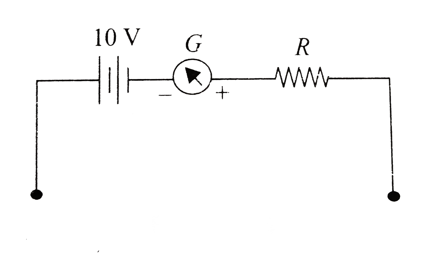
When there is an infinite resistance, there is zero current through galvanometer and it points in middle. If the test leads of this meter are directly shorted, (zero resistance) galvanometer will give full deflection.
Galvanometer specification
Resistance of galvanometer =100Ω
Fullscale current =0.5mA
Total number of division =40 .
View SolutionQuestion 189
An ohm meter measures the resistance placed between its leads. This resistance reading is indicated by a galvanometer that operates on current. The ohm meter has an internal source of voltage to create the necessary current to operate the galvanometer and also has approproate resistor to allow just right amount of current through galvanometer. A simple ohm meter is shown here.

When there is an infinite resistance, there is zero current through galvanometer and it points in middle. If the test leads of this meter are directly shorted, (zero resistance) galvanometer will give full deflection.
Galvanometer specification
Resistance of galvanometer =100Ω
Fullscale current =0.5mA
Total number of division =40 .
View SolutionQuestion 190
An ohm meter measures the resistance placed between its leads. This resistance reading is indicated by a galvanometer that operates on current. The ohm meter has an internal source of voltage to create the necessary current to operate the galvanometer and also has approproate resistor to allow just right amount of current through galvanometer. A simple ohm meter is shown here.

When there is an infinite resistance, there is zero current through galvanometer and it points in middle. If the test leads of this meter are directly shorted, (zero resistance) galvanometer will give full deflection.
Galvanometer specification
Resistance of galvanometer =100Ω
Fullscale current =0.5mA
Total number of division =40 .
if we want to measure 5 Omega Resistance than what is the position of needle View SolutionQuestion 191
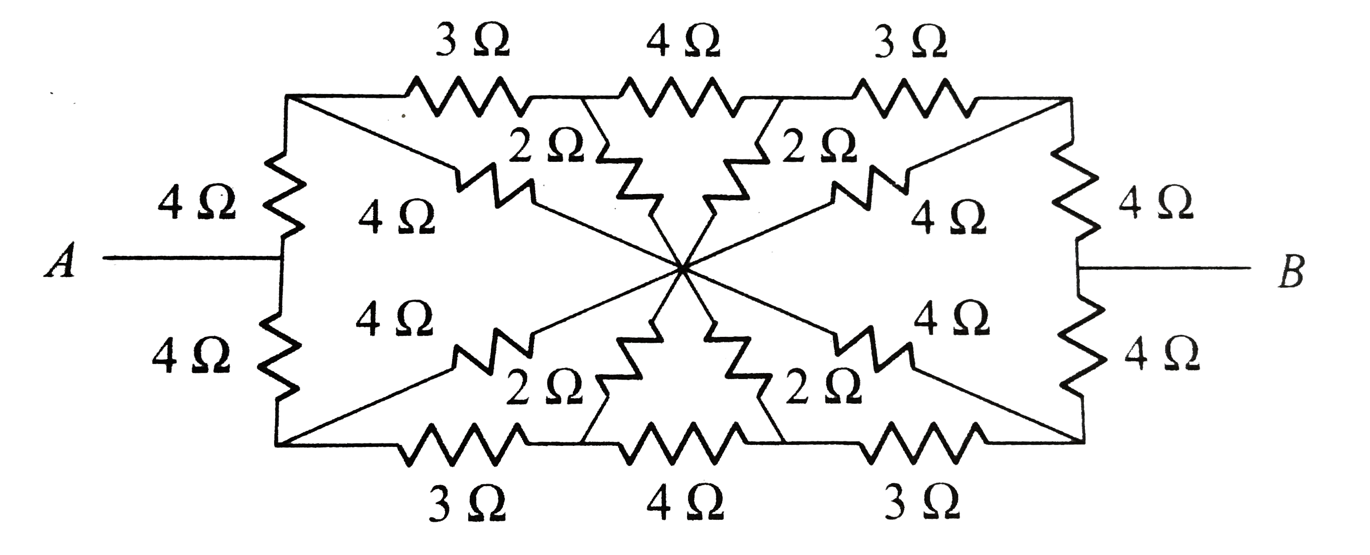
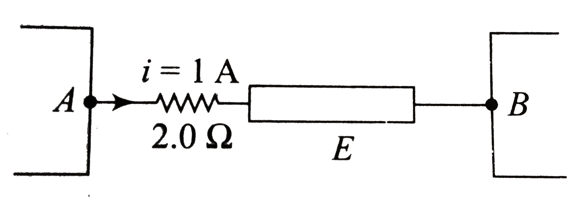
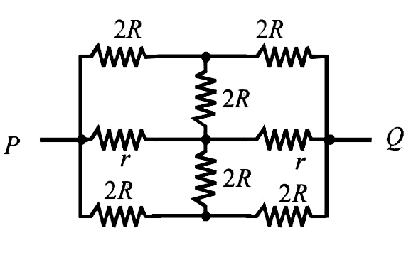
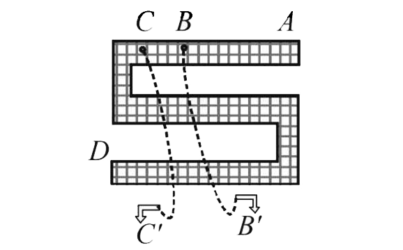
A 10 m long nichrome wire having 80Ω resistance has current carrying capacity of 5 A. This wire can be cut into equal parts and equal parts can be connected in series or parallel. What is the maximum power which can be obtain as heat by the wire from a 200 V mains supply? (in kW) View SolutionQuestion 195
The current in a conductor and the potential difference across its ends are measured by an ammeter and a voltmeter.The meters draw negligible current.The ammeter is accurate but the vlotmeter has a zero error(that is ,it does not read zero when no potential difference is applied).Calculate the zero error if the readings for two different conditions are 1.75A, 14.4Vand 2.75a, 22.4V.View SolutionQuestion 217
A wire of length L and three identical cell of negligible internal resistance are connected in series. Due to the current, the temperature of wire is raised by ΔT in a time t. A number N of similar cells is now connected in series with a wire of the same material and cross section but of length 2L. The temperature of wire is raised by the same amount ΔT in the same time t. The value of N is View SolutionQuestion 233
A resistance of 2Ω is connected across one gap of a meter bridge (the length of the wire is 100cm) and an unknown resistance, greater than 2Ωis conneted across the other gap. When these resistances are interchanged, the balance point shifts by 20cm. Neglecting any corrections,the unknown resistance is View SolutionQuestion 237
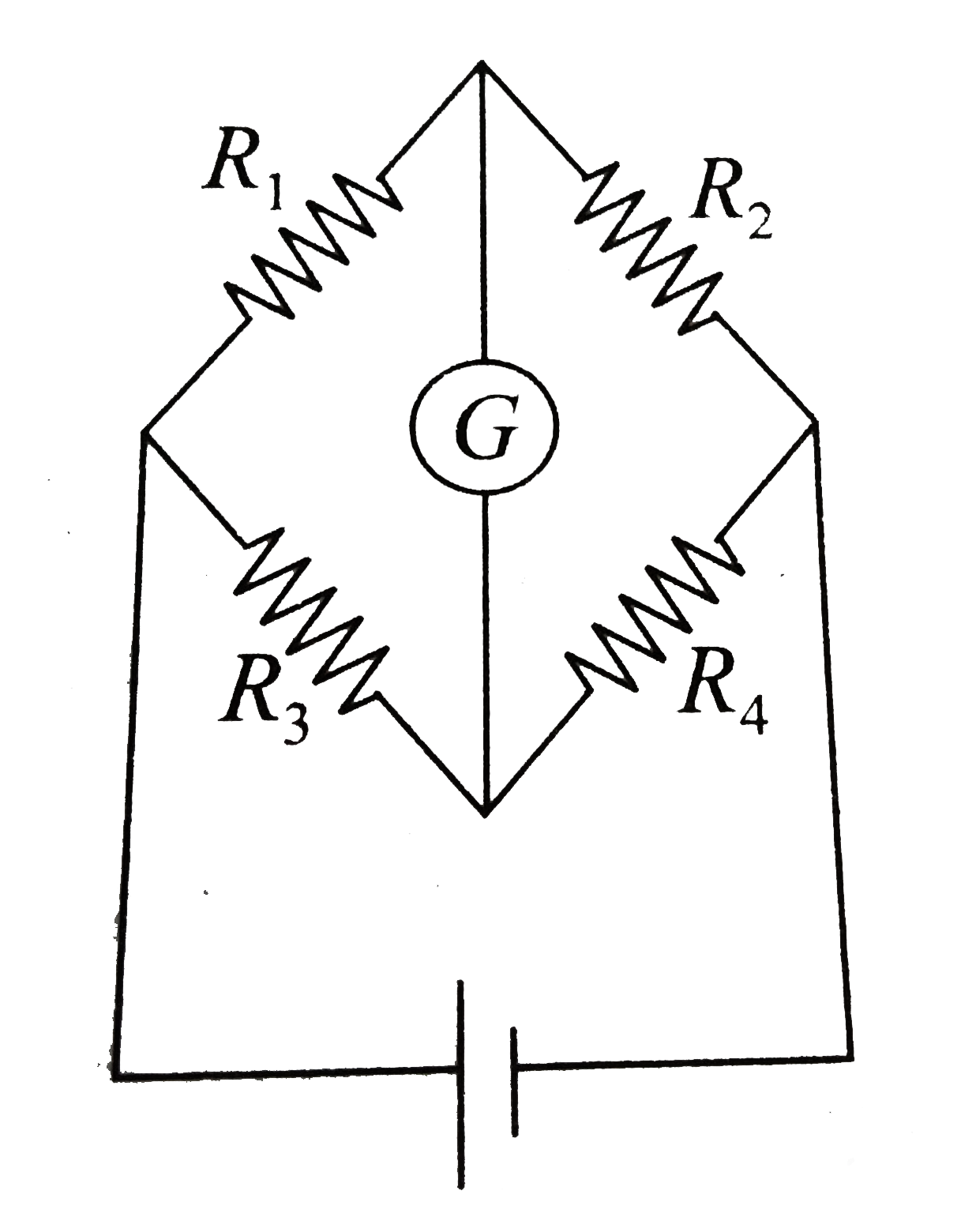
Statement-1 : In a Meter Bridge experiment, null point for an unknown resistance is measured. Now, the unknown resistance is put inside an enclosure maintained at a higher temperature. The null point can be obtained at the same point as before by decreasing the value of the standard resistance.
Statement-2 : Resistance of metal increases with increase in temperature. View SolutionQuestion 239
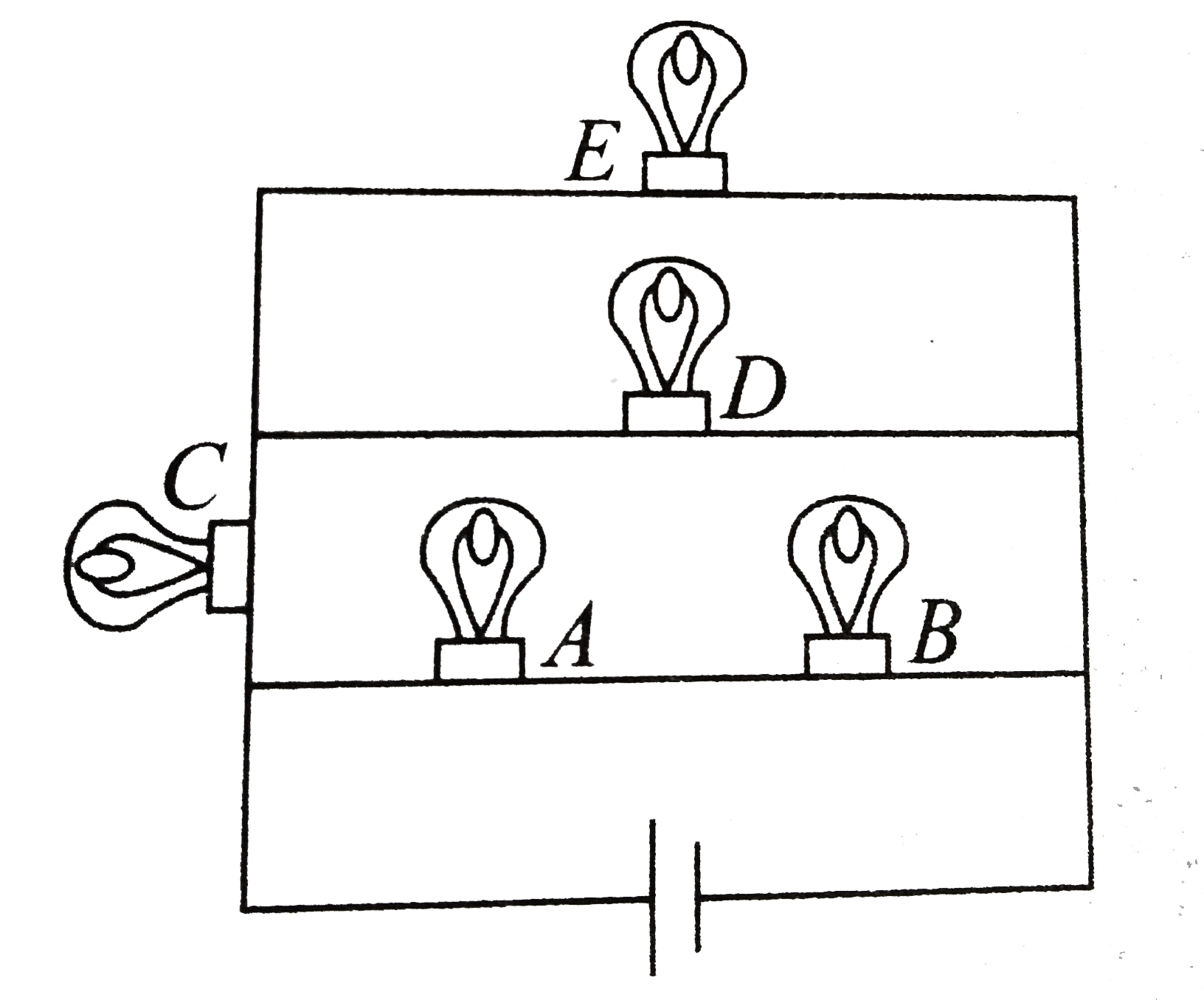
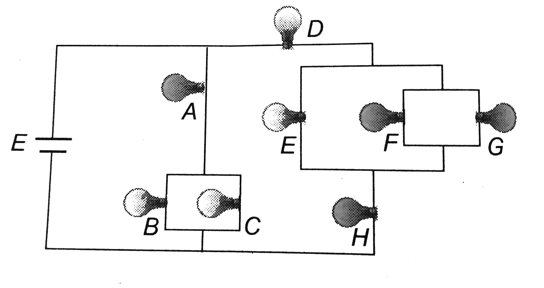
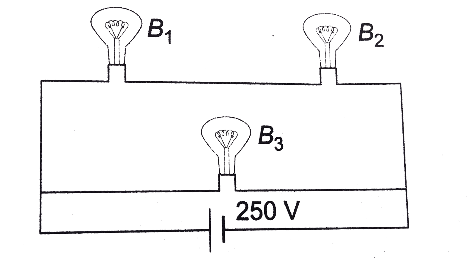
Incandescent bulbs are designed by keeping in mind that the resistance of their filament increases with the increase in temperature. If at room temperature, 100W,60Wand40W bulbs have filament resistances R100,R60andR40, respectively, the relation between these resistances is View SolutionQuestion 243
Read the following statements carefully
Y: The resistivity of semiconductor decreases with increases of temperature.
Z: In a conducing solid, the rate of collisions between free electrons and ions increases with the increase of temperature.
Select the correct statement (s) from the following
a. Y is true but Z is false b.Y is false but Z is true
c.Both Y and Z are true d. Y is true Z and Z is the correct reason for Y View Solution


 .
. 
 .
. 
 .
.  .
. 
 .
.  .
. 

 .
. 
 .
. 
 .
. 
 .
.
 .
. .
.
 .
. 
 .
.